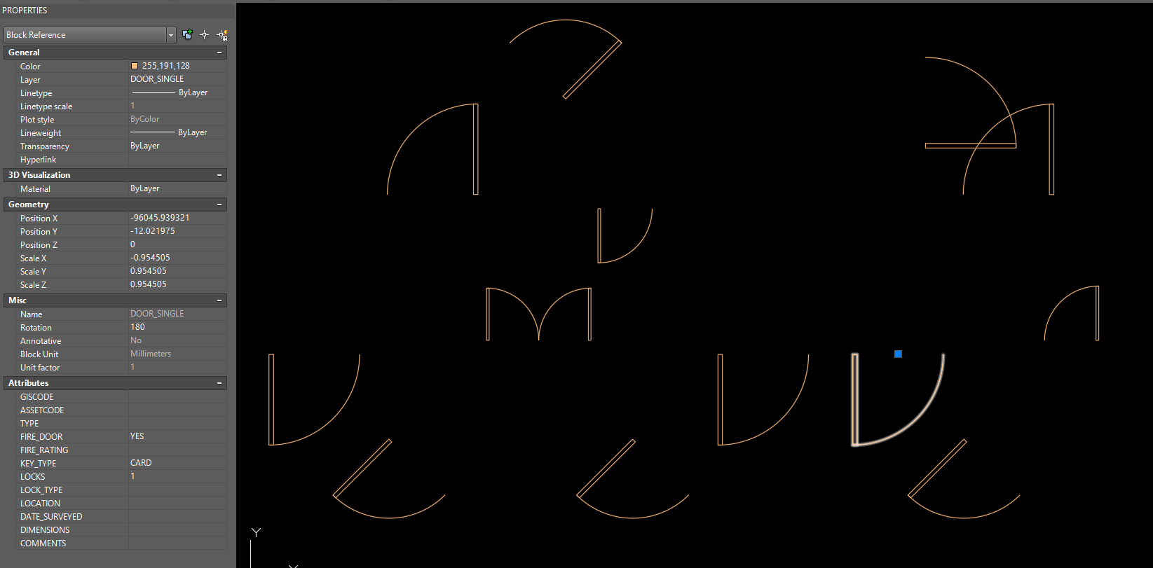
I'm sure this is likely to be a bug, I've spent a long time trying to figure out why this doesn't work.
I have a workspace that reads CAD blocks (doors) from a .dwg file into FME, exploding these on input (as I want to use the original shape in GIS). It then aggregates these shapes (lines/arcs), and merges the insert point coordinates/attributes of the exploded block to the attributes of the aggregated shape. I then use the VertexCreator with these coordinates stored on the aggregated shape to turn it back to a point. This workflow is needed so I can hopefully have a smooth transfer of data from CAD to GIS and back again.
The problem is when these blocks are recreated using the CAD writer, they do not represent the original blocks that are read in, even though all the attributes are identical. It is inconsistent with how the blocks use the x/y scale; if a negative x/y scale is used the block will be created as if this is positive so the block is mirrored. If you then reset all the x/y scale values to 1 for these blocks, the block you end up with is different, which shouldn't be possible. I'll attach a before and after so hopefully this makes more sense:
Original CAD:
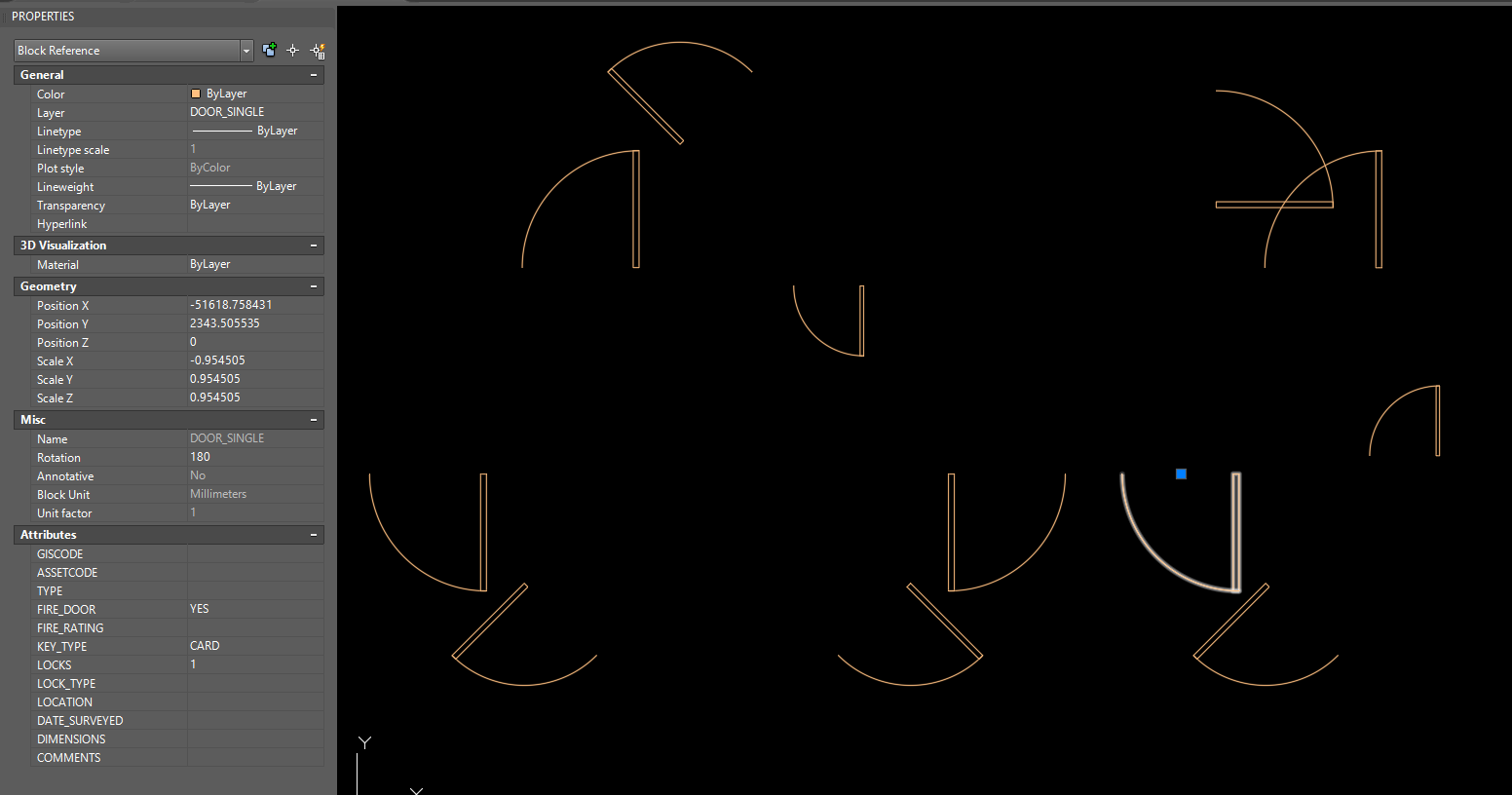
Recreated CAD: