
What I need to do is first set the flow direction for the pipeline and from there I can use transformers to copy attributes from a point feature and copy it to the line feature that is behind it (flow direction). The line segments are not collected in a numerical object id order, so I can't figure out how to set a flow direction to be able to set attribute values that both feature classes share and should be the same.
*GDB feature classes*
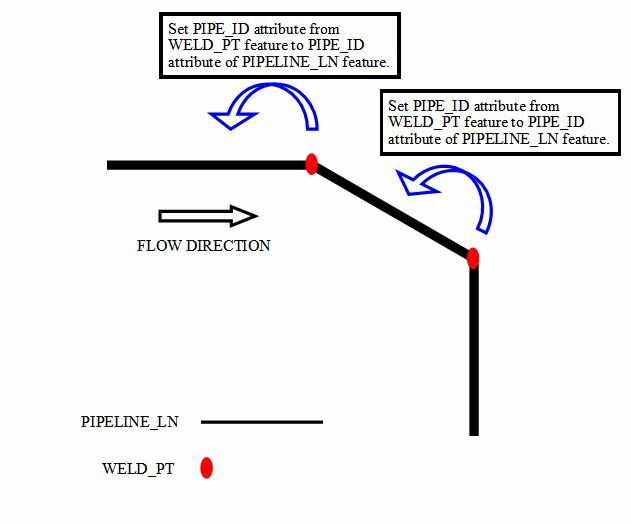
Example: