Question

CAD to Excel


I'm still quite new and struggling on the first hurdle, any help anyone could provide would be much appreciated.

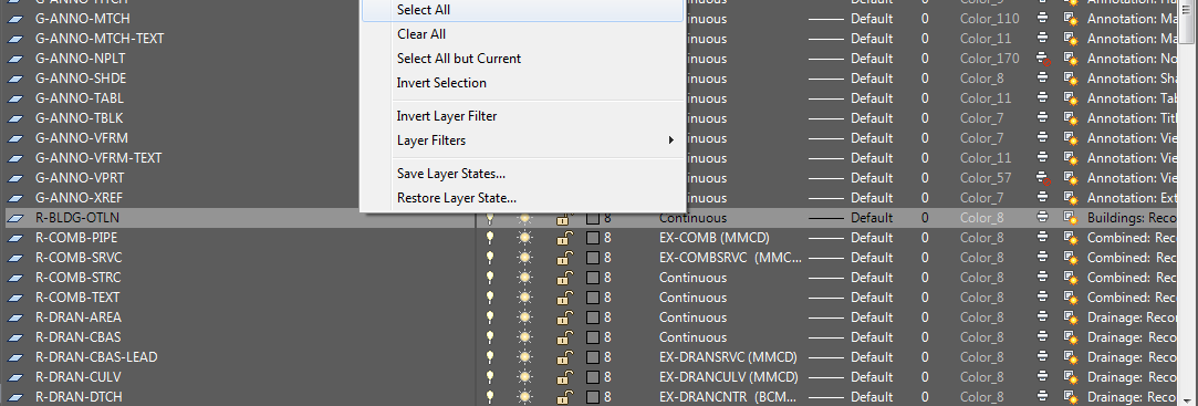
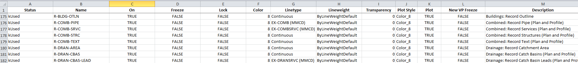
I have a CAD (DWG) file with multiple Layers. The Layers contain settings such as Linetype, Lineweight, colour etc. I would like to get the Layer setting out to and Excel spreadsheet.

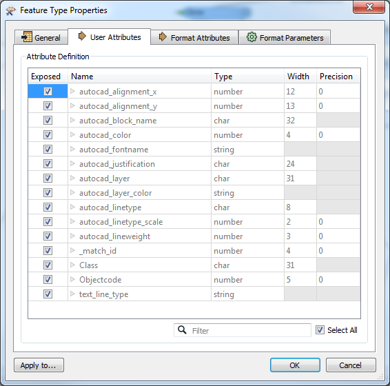
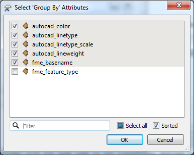
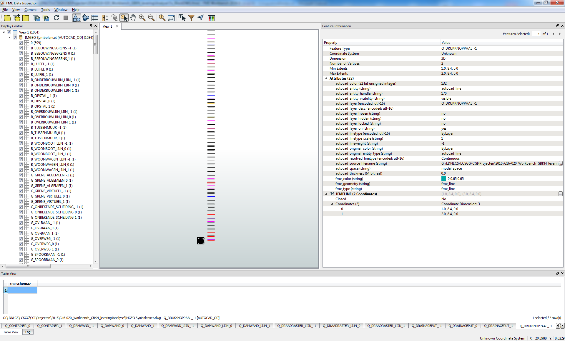
I've opened a CAD file, exposed only the relevant Layer attributes but nothing seems to flow through to the transformers or even into an inspector.


15 replies

Userlevel 4
Badge +25

You're writing out to an Inspector, so the results won't actually get written to Excel but rather they'll be shown in the FME Data Inspector.

Try adding an Excel writer (if you haven't done so already), or set up a new workspace using the generate option, this will automatically set up reader and writer feature types.

Hope this helps. You may also want to consider going through some of the recorded training courses on Safe's website.

Thanks for your help @redgeographics but not quite what I was after.

It would appear the problem was that when taking a CAD file into FME the only layers read are those which contain points, geometry etc. I'm not sure if it's a setting or whether that's just how FME is currently set up.

That's why when I hit "Run Translation" nothing was passing through as while the layers existed they were empty.

For some reason the Important layer attributes such as Lineweight, Linestyle and Linecolour do not seem to come through at all.

Badge +3

..he just said nothing flows trough..

Looks like the layers don't contain objects.

Its like a previous question about blocks with no objects assigned to them.

FME seems only able to read such information when there is at least one object in the layer(s).

That's why my template all contain 1 object per layer and or per block. To faccilitate fme.

So you'll have to add a object per layer.

(even data extraction in AutoCAD requires objects on the layers)

(there are some lisps out on the cad fora there to help you out if you have a lot of layers.)

Userlevel 4
Badge +25

You're right, if there's nothing on the layer in Autocad, nothing will be written to Excel.

Your (FME) screenshot does show attributes with lineweight, -style and -color so they are present on a feature level, but there needs to be a feature otherwise you won't see them in Excel (or in the Data Inspector for that matter)

@gio you might know the answer to this, would it be possible to create a DWG which contains Layers where the Layer info has been extracted from an excel file?

Badge +11

While in AutoCAD

  1. Open the Layer Properties Manager.
  2. Hover over a layer, Right button "Select All"
  3. Ctrl+C
  4. Open Excel and paste

Or if you want some excitement, parse thru a DXF file with a TEXT_LINE reader

Haha very good point @hlouie.

The main point in me trying to work out how to get the Layers out of AutoCAD and into Excel was so that I could also go the other way and create AutoCAD files with only the Layers I required driven by an excel file.

Does anyone know if this is possible in FME?

Badge +3

@michaeltfl

Hi All,

Yes it is possible to do that.

You create a excel which contains the info like in

Then count the rows (non empty)

Create a line for each row using 2 vertexcreators (Replace point followed by add point)

To make them visible for yourself you can do x=1 and

In my case I use Class as layername so you use a autocad writer With layer Name = @Value(Class)

For symbols You can do same> If you have them in seperatre dwg's you can use a acad reader in advanced mode . THen aggregate the parts of the symbols

Then for order align them neatly by centerpoint.

I use a affiner a=1,b=0, c=-(@Value(_xmin)+(@Value(_xmax)-@Value(_xmin))/2)

and d=0,E=1,F=-(@Value(_ymin)+(@Value(_ymax)-@Value(_ymin))/2)

Put all symbols on layer 0 (mandatory)

Use acad writer again or do both processes in one workbench(how I did it).

My property and symbol dwg looks like

I have all symbols on 0,0.

This you can then use in your workbench.

The blocks I acces with a dwgstyler and setting a templatefile in the writer parameters (navigator panel).

The line_width etc. i acces trough the excelfile by setting the writer output layer to @Value(output_layer) wich I fill by the value Class ( see excel properties in pic).

There is one thing you can't do with fme tough:

Setting layer to color by layer.

For this I use a lisp which I run after the dwg template is created.

Badge +3

dgdlay-kopielsp.txt

b20-kopielsp.txt

I see i used 2 lisps.

1 to put blocks on layer 0 (B20; Block to Zero)

And 1 to set color by layer.(dgdlay) (dgd is name of dataset I was working on)

U must load the lisps into your autocad. (command line CUI)

I used the autocad for a to figure it out, so its by that community's help too...:)

(hope I posted the correct ones as I have a map full of these..)

Badge

While in AutoCAD

  1. Open the Layer Properties Manager.
  2. Hover over a layer, Right button "Select All"
  3. Ctrl+C
  4. Open Excel and paste

Or if you want some excitement, parse thru a DXF file with a TEXT_LINE reader

Great trick I did not know of!


Hi @gio

Thanks for the extensive work you've put it, I'm just trying to run through it now and I'm finding it a bit hard to follow.

"Create a line for each row using 2 vertexcreators (Replace point followed by add point)" - If I want to create a line do I need to use a PointConnector Transformer afterwards?

"To make them visible for yourself you can do x=1 and "- should this read y=

@XValue(_count)*0.2?

"In my case I use Class as layername so you use a autocad writer With layer Name = @Value(Class)" - When you say autocad writer do you mean within FME? and if so I can't see a "With layer Name" option within the CAD Writer, am I missing something?

Once again thanks for your help so far you've really gone over and above.

Badge +3

@michaeltfl

HI.

I create a line for each type u need in a template.

x and y values are ones I used. In vertexcreator set them to the values mentioned using the arithmic editor. (this is to make them visible in the template instead of all lines on top of eachohter. Not nescesary for mapping.)

Using a vertex creator

with "replace with point" and then with "add point" creates 1 line. No connector.

Yes I do mean the FME AutocadWriter. You can set the layer name in the GEneralParameters" tab

"Layer Name"

This should be the name you later will refer to to get the info out. (Fanout Expression).

Here is a pic, it does not require many transformers.

Badge +3

Here is the bit treating block creation.

Its in same workspace as the previous pic.

Both write to the same autocad to create a single template file.

Resulting in this autocad file

Badge +3

all block symbols stacked on origin. So all have 0,0 at centre.

Thanks @gio you've been incredibly helpful.

Reply