Question

AutoCAD test writing problem


With great help from the folks here I've started being productive in writing Mapinfo tables to DWG. However I've run into a problem writing text.

I have a number of layers that need to have labels applied. One is a polygon layer. The goal is to write a piece of text in the centroid.

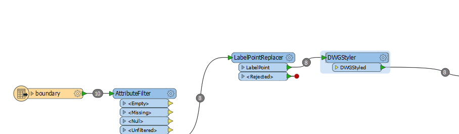
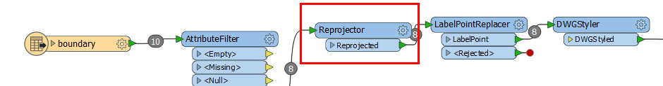
To achieve this I've used a LabelPointReplacer to get the something like the centroid. From here it gets bit weird.

For the life of me I cannot get the labels to orient with zero(0) rotation. Initially the label wanted to align with the first vector in the polygon so that was understandable.

I tried to overcome this by using a DWGStyler but this seems to have no effect.

My suspicion is that my source tables are Lat\\Long and the CAD is GRID projected. However there must be a way to set the rotation to CAD zero.

Any assistance appreciated.


7 replies

Badge +3

Hi @andyew,

If you think that the problem is the coordinate system, you could start your model with a 'CoordinateSystemRemover' transformer. This removes all coordinate systems from you data. However I would not expect that to be the problem, since the data will be written in the same system as the data is being read. Using the CoordinateSystemRemover doesn't do any harm, so you could start trying that.

Also you could check the settings of your LabelPointReplacer. It has an option for 'Always Rotate Label'. If you set that one to 'No', it should stay horizontal.

I hope this helps.

Badge

The labels are oriented in data inspector as well?


It could have something to do with settings in your DWG file, or a DWG-template that you have specified in FME?

The labels are oriented in data inspector as well?


It could have something to do with settings in your DWG file, or a DWG-template that you have specified in FME?
Thanks @lars_de_vries and @jneujens. So to answer both comments, when viewing the rotation value in the Inspector the rotation is exactly 0. However the coordinates in the source are geographic.(Lat\\Long) my requirement is to produce UTM Grid coordinates. So as I suggested earlier I suspect that in the process of converting the insertion point coordinate to UTM grid is also taking 0 degree rotation and applying a conversion. The issue here is that 0 degrees in GIS is North and measured clockwise. Whereas 0 degrees in CAD is "East" and measured Counter clockwise. If I was at the equator I would probably be OK, but latitudes north and south tends to produce distortion. It's not feasible to remove the coordinate system as suggested as that is a requirement of the conversion. However is there a way to pre-compute the converted coordinates and then write the "non-spatial" coordinates to the DWG?
Badge +3

Hi @andyew,

if you want to change the coordinate system, you should use a Reprojector transformer. If the coordinates are well set in the MapInfo file, you only need to set the Destination Coordinate System.

I would start your model with adding that one directly after reading.

I hope this will get you a step further.

Badge +3

I extract the label point and then set the "autocad_rotation" attribute to 0 (in my case mostly an angle I specify by attribute or calculation). Then you are not dependend on object orientation extracted by fme.

The rotation from the styler has some issues when using an attribute or arithmetic, I never use that one.

Because the always rotate option says.

"The label is rotated to prevent it from appearing upside down." So it always rotate based on the object it is extracted from (I assume) unless it is horizontal..

Hi @andyew,

if you want to change the coordinate system, you should use a Reprojector transformer. If the coordinates are well set in the MapInfo file, you only need to set the Destination Coordinate System.

I would start your model with adding that one directly after reading.

I hope this will get you a step further.

This was the solution. By using the Reprojector and coverting geographic to UTM Grid BEFORE using the LabelPointReplacer the rotation is calculated based on UTM GRID rather than being converted on the fly to GRID by the ACAD Writer. This had the added benefit of allowing the Text height to be specified in DWG units (metres in this case) rather than fractions of a degree and then converting to GRID. Very robust @lars_de_vries. Thanks.

Badge +3

Hi @andyew,

if you want to change the coordinate system, you should use a Reprojector transformer. If the coordinates are well set in the MapInfo file, you only need to set the Destination Coordinate System.

I would start your model with adding that one directly after reading.

I hope this will get you a step further.

Hi @andyew, you're welcome! That's what we are here for.


Reply