Question

Coordinate system tester CAD drawing


Badge +5

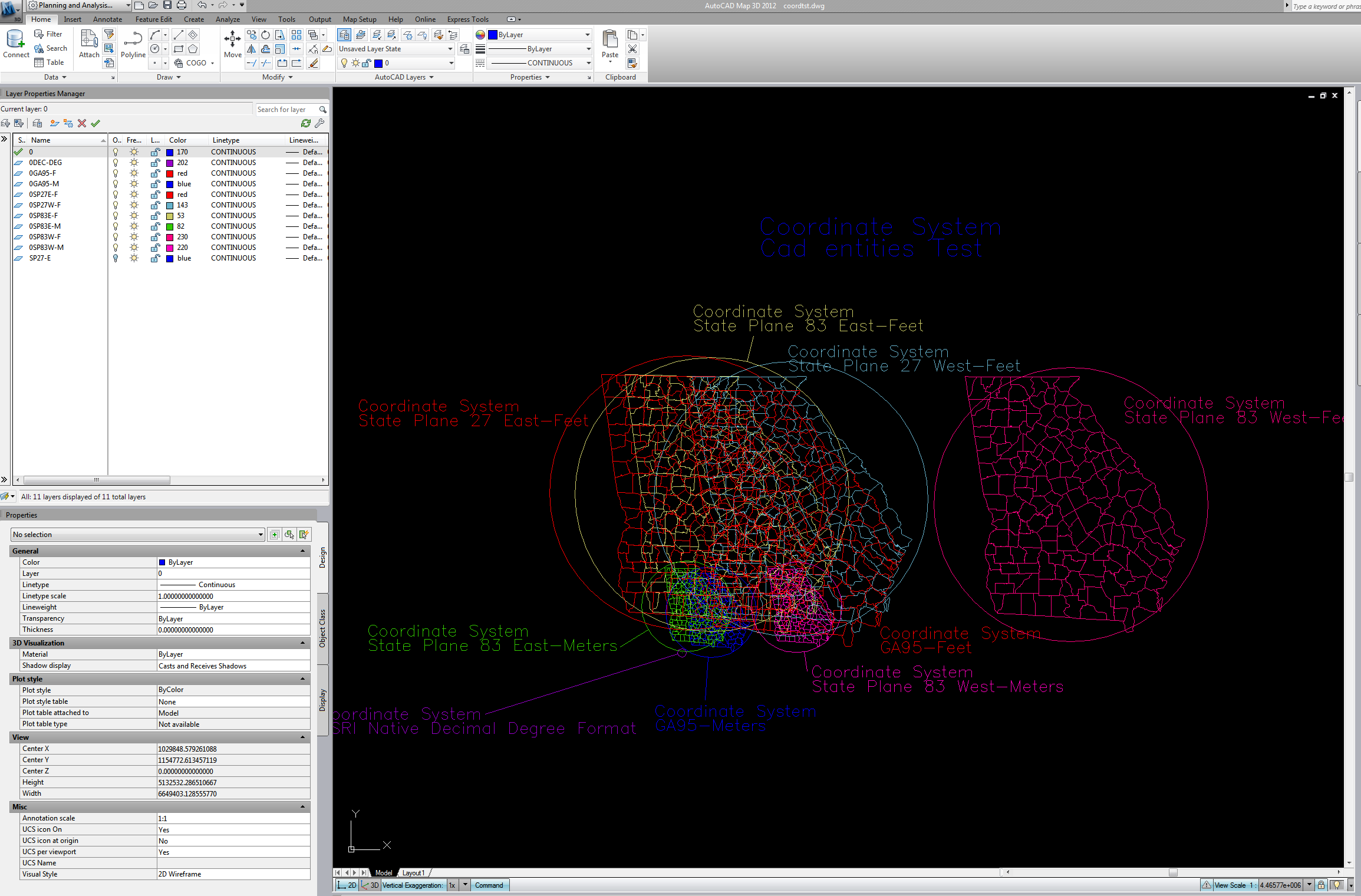
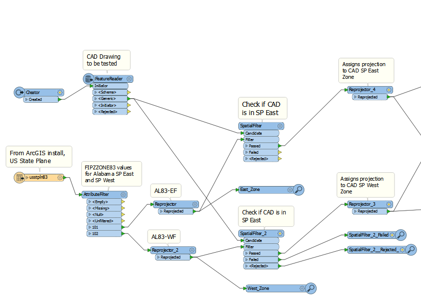
Can I use FME to build a DWG file the screenshot below?

I'd like to create a similar cad file for Alabama. I can use this drawing to validate cad data sent by our engineers to QA prior to transformation. I've been using reprojector and writing to DWG but the line work still lands on top of each other.


3 replies

Userlevel 1
Badge +12

So you need to set the reprojector with the coordinate system you are reading (there needs to be a coordinate system on the features being projected) and then the output coordinate system. Now before you write out to the CAD file, use "CoordinateSystemRemover" to get rid of the coordinate system, but leave the XY positions in the project location. Also make sure your your writer doesn't have a coordinate system set.

Badge +5

So you need to set the reprojector with the coordinate system you are reading (there needs to be a coordinate system on the features being projected) and then the output coordinate system. Now before you write out to the CAD file, use "CoordinateSystemRemover" to get rid of the coordinate system, but leave the XY positions in the project location. Also make sure your your writer doesn't have a coordinate system set.

Your logic will work, I'll test it and let you know. Thanks!

Working on my project I found an option without using this dwg file to determine project location. I'd still use your logic since I love to build the CAD for AL since I know how valuable it is even as a QA tool and a reference for training.

My solution in next comment.

Badge +5

To solve my problem, I mimicked ArcMap logic into FME. In ArcMap when a CAD file with an unknown SRS is added, you can keep changing the data frame projection to your state's appropriate projections - need to try feet and meters too - and if the CAD has a SRS, CAD features will line up on the right location of the state.

In FME, using state shp from ArcGIS install, I filter the SP zone features for AL and reprojected each for every coordinate system I want to test, I intersected the CAD on each reprojected feature to determine the SRS used for CAD.

Most CAD drawings submitted by our vendors in the last 15 years or more this process will work. There will be exceptions for drawings drafted with local coordinates - a custom projection using georeferencing in ArcMap is the best solution for these drawings.

In my attached image for the state of Georgia it required more coordinate systems because of a custom projection created by the state's DOT and the state based utility Georgia Power called GA95.

The solution removed all guess work related to locating the project and then I added a few more transformations to complete our end user requirements to filter ROWs - acquired and current; properties/parcels, construction limits, and contours.

Attached image is my FME canvass for the projection/location solution.

Reply