Solved

Surface modeller - Units of surface tolerance

  • 7 August 2018
  • 6 replies
  • 18 views

Badge

Hi FMErs,

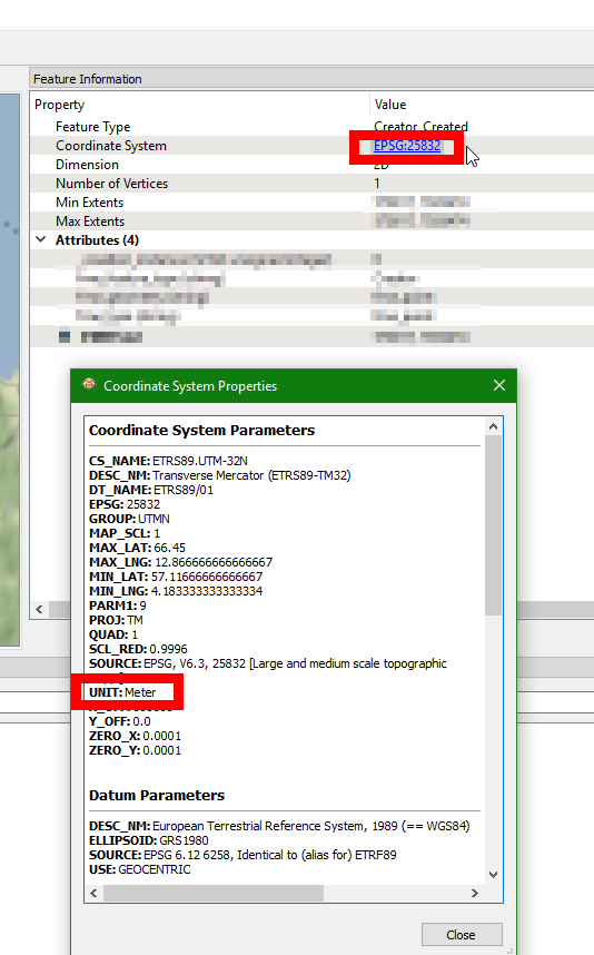
I have an AutoCAD dxf of 2D contours with elevations at 1m increments in an attribute.

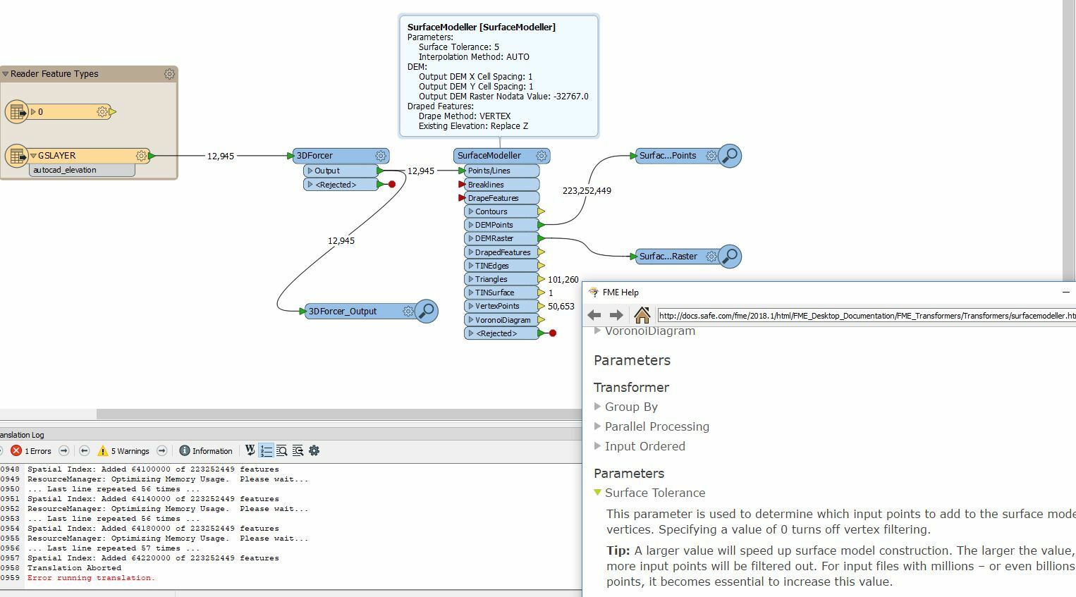
When trying to create a surface DEM and points with the surface modeller, the tolerance parameter needs to be tuned to an appropriate value to reduce the number of vertices. Question is, what are the units of the tolerance parameter ?

Thanks in advance

icon

Best answer by hollyatsafe 10 August 2018, 01:27

View original

6 replies

Userlevel 2
Badge +17

Hi @pat_uow, as far as I know, the units of the Surface Tolerance would be considered as the same as the units of z-coordinates in the input geometries. If the units of z-coordinates in the input geometries are meters, for example, you can assume that the units of the Surface Tolerance are also meters.

Badge +21

You can figure it out in the FME Data Inspector by looking at the 3DForcer_output. Select one feature - click the Coordinate system (in blue below) and check the UNIT. I believe this will be the units used. If you need to change this, for instance if you have an unknown coordinate system you can cheat by using a LocalCoordinateSystemSetter and set the Projection Units to Meters before the SurfaceModeller.

Badge

You can figure it out in the FME Data Inspector by looking at the 3DForcer_output. Select one feature - click the Coordinate system (in blue below) and check the UNIT. I believe this will be the units used. If you need to change this, for instance if you have an unknown coordinate system you can cheat by using a LocalCoordinateSystemSetter and set the Projection Units to Meters before the SurfaceModeller.

Apologies all for the terminology I have used in the question. I agree that the units of Z of the incoming 3D polyline features to the surface modeller are in Metres. The question is related to the surface tolerance parameter within the surface modeller transformer itself. An increase in this parameter is (according to the help) supposed to reduce or filter the number of vertices used for surface calculation. My testing thus far it seems that this tolerance parameter has no effect when the incoming features are 3D polyline - so I was seeking guidance on what reduction or filtering units the parameter is designed to deliver.


Userlevel 2
Badge +17

Hi @pat_uow, as far as I know, the units of the Surface Tolerance would be considered as the same as the units of z-coordinates in the input geometries. If the units of z-coordinates in the input geometries are meters, for example, you can assume that the units of the Surface Tolerance are also meters.

How large is the difference between the elevations (z values) of adjacent contour lines?


Is the surface tolerance value you have set is greater than the difference?


Badge +2
Hi @pat_uow,


The tolerance parameters should definitely have an affect on polyline features, are you able to provide a small sample dataset for me to do some testing on. As if this isn't working then you've spotted a bug!


Badge +2

Hi @pat_uow,

The Surface Modeller builds up a Triangulated Irregular Network (TIN) using the points that are provided. As it adds each point it compares the difference between the Z value of the point being added and the Z value at that point in the existing model. If the difference is greater than the tolerance specified then the point is added to the model and the TIN is recalculated to include this new point. If the Z value of the point is less than or equal to the tolerance specified then the point is not added to the model. The effect is that the point density of the model is higher in areas where there is great elevation change (ie. Mountainous regions). The opposite can also be said that the point density is lower in flat areas where there is little elevation change (flat lands, water bodies, etc.)

Reply