Question

Help: 2D lines to 3D using (some) known 3D points


Badge +12

Hi!


I've been struggling with this task for a while now and need some help.


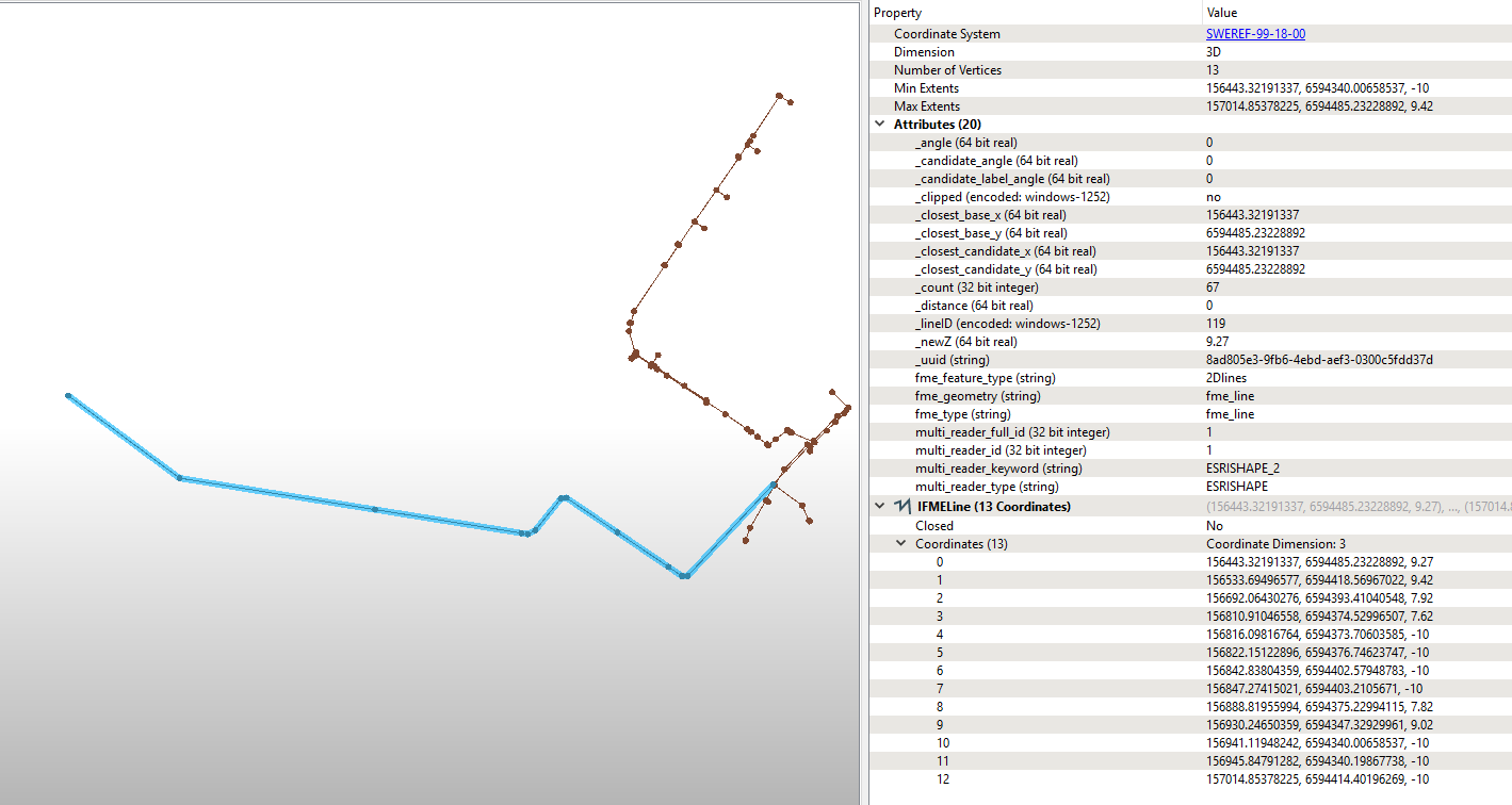
I have a set of 2D lines (sewage lines if anyone is interested), with a "_lineID" attribute.


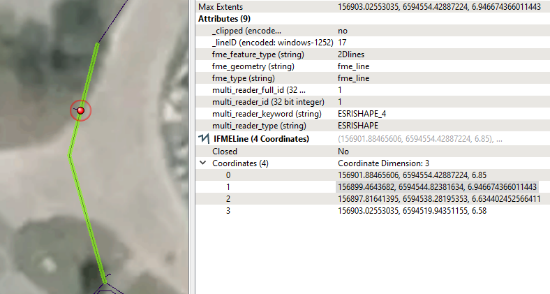
I also have set of known 3D points on those lines. Some are on end nodes, some are on a vertex. These points also have the corresponding "_lineID" attribute.


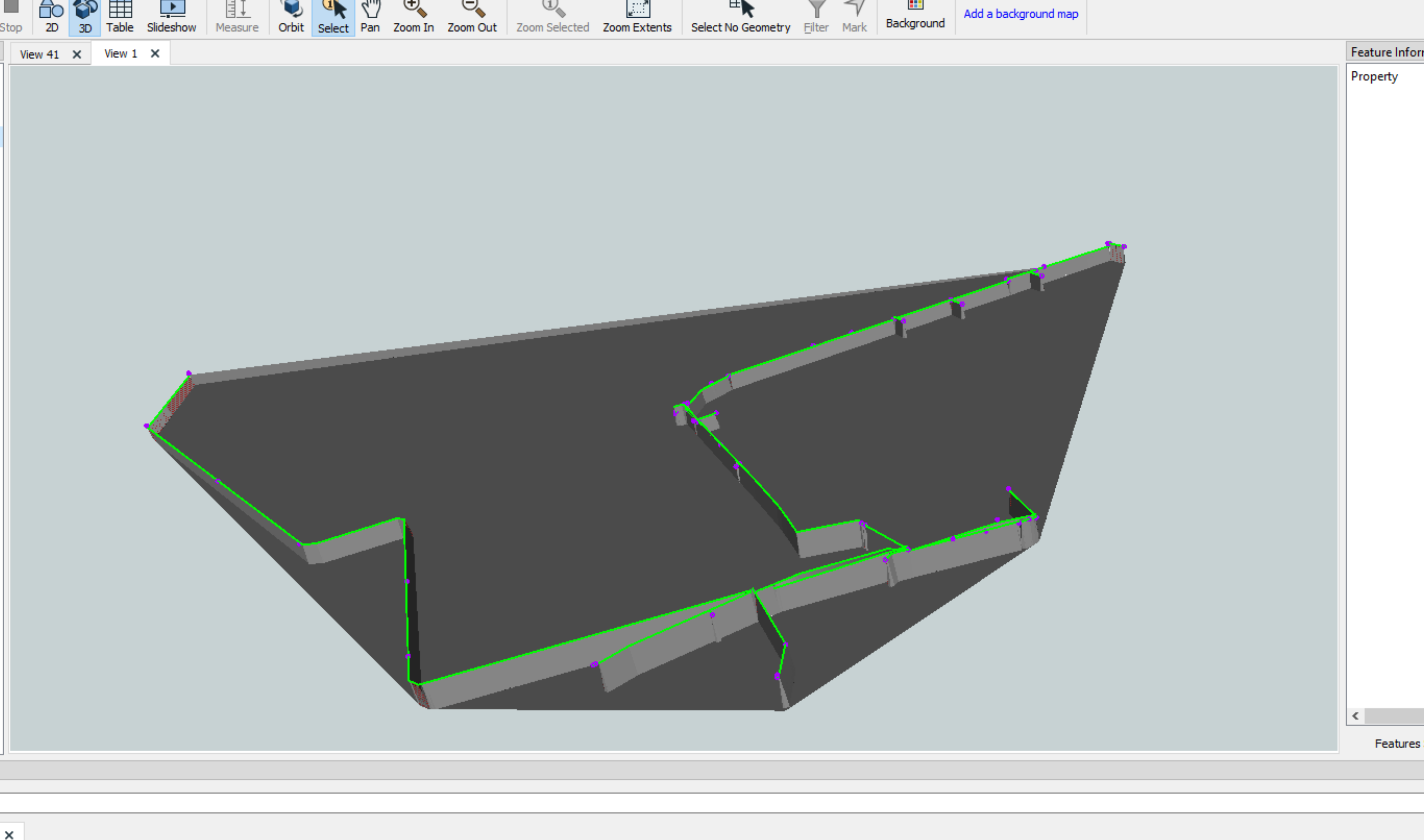
Now I want to use these known points to get the lines into 3D, interpolating any line vertices in between which doesn't have a known height. However, I'm having problems with this.

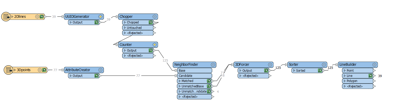
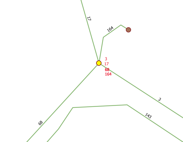
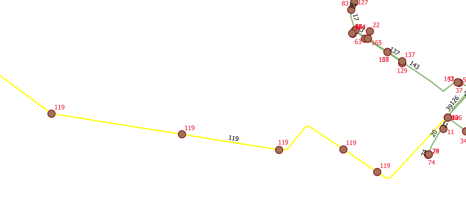
I've tried to implement a NeighborFinder with a Group By: _lineID to help where there are points located in the same XY position, only differing in height (see attached screen shot below - the yellow dot is actually four points in the point file, each with a different "_lineID").


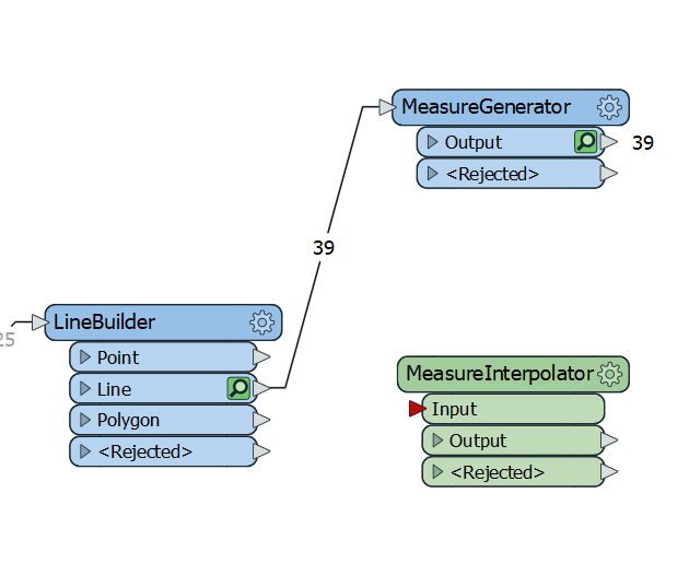
This is followed up by a 3DForcer. This part works fine, but I can't manage to re-build the lines again (using a LineBuilder) since there are now both these 3D points and vertices on the original lines which are only 2D points.


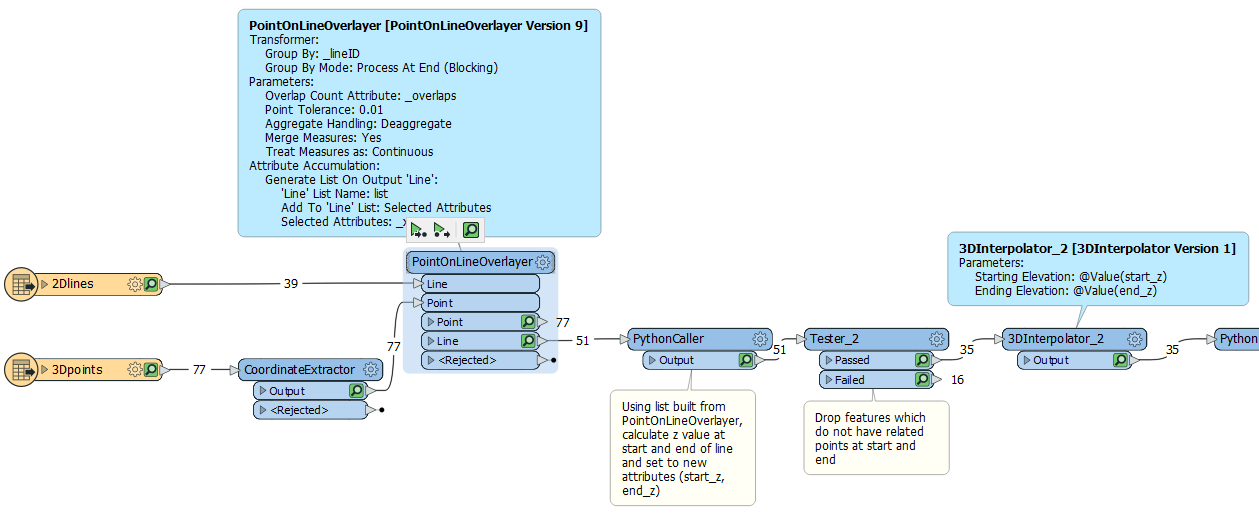
The 3DInterpolator transformer is also needed I guess, but it only works on a line between two known 3D points, disregarding any known point in between. A line with several known points (like line 119 in the screenshot below) would have to be divided first - maybe with a PointOnLineOverlayer.


I've also tried the SurfaceDraper to "drop" a line on the known 3D points, but it has several problems; 1) it needs at least three known points on the line to form a surface (many lines only have two known points), and 2) if you have a line that is bending in 2D, points outside the surface created by the known 3D points will be given extrapolated heights and not correctly interpolated ones.

My question is similar to chrst's question (did you develop it further, @chrst ?), but I haven't been able to implement it correctly in my workspace.


Anyone that can help me with this?


Zipped file with a small sample of lines and points are attached:

25 replies

Badge +21

Hi @jonas_nelson

What about using a Triangulator from the 3D-points first to create a TINSurface and then use the SurfaceDraper with the TINSURFACE as Points/lines and the 2D-lines as DrapeFeatures?

Badge +21

surfacemodeller.fmwt

Trying with the SurfaceModeller directly

Badge +12

surfacemodeller.fmwt

Trying with the SurfaceModeller directly

Thanks @sigtill but you are using version 15 of the SurfaceModeller. I'm running on FMW Workbench 2018.1 and can't read it. (Sadly, I am not authorized to update the software on the computers in our organisation).


Assuming there's no major changes in the transformer, I've tried with the SurfaceModeller in FME 2018.1, but the result gives the same problem - the surface is created by the 3D known points, and the rest of the 2D vertices of the lines are then just draped on top of the surface, not linearly interpolated along the lines as I would like them. Remember, these are sewage lines, and they should have a rather constant slope between the known points. They should not go up and down.


....And there's still the problem with the 3Dpoints stacked on top of each other.
Badge +12

Hi @jonas_nelson

What about using a Triangulator from the 3D-points first to create a TINSurface and then use the SurfaceDraper with the TINSURFACE as Points/lines and the 2D-lines as DrapeFeatures?

You would still have a problem creating a correct TIN surface where there are several points stacked on top of each other, as in my example.


You'd need a separate TIN for every line - and some lines only consist of two points, and other lines have vertices "outside" the TIN created by the known points.
Badge +21

Thanks @sigtill but you are using version 15 of the SurfaceModeller. I'm running on FMW Workbench 2018.1 and can't read it. (Sadly, I am not authorized to update the software on the computers in our organisation).


Assuming there's no major changes in the transformer, I've tried with the SurfaceModeller in FME 2018.1, but the result gives the same problem - the surface is created by the 3D known points, and the rest of the 2D vertices of the lines are then just draped on top of the surface, not linearly interpolated along the lines as I would like them. Remember, these are sewage lines, and they should have a rather constant slope between the known points. They should not go up and down.


....And there's still the problem with the 3Dpoints stacked on top of each other.

No large changes on that transformer - and I missed the point of 3D-points stacked on top. The Densifier can create more points along the lines. I`ll see if I can come up with another suggestion

Userlevel 1
Badge +10

Thanks @sigtill but you are using version 15 of the SurfaceModeller. I'm running on FMW Workbench 2018.1 and can't read it. (Sadly, I am not authorized to update the software on the computers in our organisation).


Assuming there's no major changes in the transformer, I've tried with the SurfaceModeller in FME 2018.1, but the result gives the same problem - the surface is created by the 3D known points, and the rest of the 2D vertices of the lines are then just draped on top of the surface, not linearly interpolated along the lines as I would like them. Remember, these are sewage lines, and they should have a rather constant slope between the known points. They should not go up and down.


....And there's still the problem with the 3Dpoints stacked on top of each other.

Are you draping by vertex or model?

Badge +21

find_new_x.fmwt (Sorry, only FME2019)

This solution gives the lines with both 2D and 3D points. The step after this is to calculate the points that have -10 as z-value based on previous values etc. I think this can be done by using an AttributeCreator. However the problem is when the end-point of the line is unknown. So you only have Z = 21 on the first point, and unknown z on the other 4 points. Should you then interpolate between?


Also looking at the MeasureGenerator and MeasureInterpolator might help.

Sorry for not finding the finished solution, but hope that someone can be able to complete it :)

Badge +12

Are you draping by vertex or model?

I've tried both, and both give bad values. Below is an example with the SurfaceModeller set to drape by Vertex. You can see that the selected vertex gets a z-value that is higher than the ones at the endpoints, since there is another 3D point a little outside the line in question. And as mentioned, trying to group by "_lineID" won't work for lines with only two points known in 3D.


Badge +12

find_new_x.fmwt (Sorry, only FME2019)

This solution gives the lines with both 2D and 3D points. The step after this is to calculate the points that have -10 as z-value based on previous values etc. I think this can be done by using an AttributeCreator. However the problem is when the end-point of the line is unknown. So you only have Z = 21 on the first point, and unknown z on the other 4 points. Should you then interpolate between?


Thank's for all your work @sigtill , I will look at this workspace and see what I can do.


If there is a line which does not have a known point at either (or both) end, you should only keep the part of the line (if any) that can be interpolated, i.e. between two known 3D points.
Userlevel 3
Badge +18

I am fairly new to FME and always looking for interesting questions to update my knowledge!

Took me some time to make it work, and can't credit every page on this forum that helped me with this, but certainly the tips and tricks here of @sigtill helped a lot.

Probably not the most efficient way, but I think this should work:

- First I only keep the lines with at least 2 points with known height

- Known heights are transferred to the lines

- starting and ending point(s) of the lines are removed if the height is unknown (with a custom looping transformer)

- intermediate points with unknown height are interpolated (based on known heights and calculated distances): I used a python script for this because I didn't immediately find another solution

- after this, all vertices of the lines have a known or calculated height so the final 3D lines can be made

Hope this can help you.

rio2dnaar3d.fmwt

Badge +12

I am fairly new to FME and always looking for interesting questions to update my knowledge!

Took me some time to make it work, and can't credit every page on this forum that helped me with this, but certainly the tips and tricks here of @sigtill helped a lot.

Probably not the most efficient way, but I think this should work:

- First I only keep the lines with at least 2 points with known height

- Known heights are transferred to the lines

- starting and ending point(s) of the lines are removed if the height is unknown (with a custom looping transformer)

- intermediate points with unknown height are interpolated (based on known heights and calculated distances): I used a python script for this because I didn't immediately find another solution

- after this, all vertices of the lines have a known or calculated height so the final 3D lines can be made

Hope this can help you.

rio2dnaar3d.fmwt

Thanks @becchr for all the work you put into this! I'll see what I can use. Right now I can't read much of it since I run FMW Desktop 2018.1. (Hoping to upgrade it soon, after a planned upgrade of my laptop to Win 10.)

Badge +12

find_new_x.fmwt (Sorry, only FME2019)

This solution gives the lines with both 2D and 3D points. The step after this is to calculate the points that have -10 as z-value based on previous values etc. I think this can be done by using an AttributeCreator. However the problem is when the end-point of the line is unknown. So you only have Z = 21 on the first point, and unknown z on the other 4 points. Should you then interpolate between?


To @sigtill , @bcchr and the rest of you that have tried to help : I've discovered the transformer MeasureOrZvalueInterpolater, which - I believe - should be able to interpolate missing z-values in line vertices. But now I have the problem of how to turn these "-10" values into <NULL> values so the interpolater can do it's magic. Any suggestions? CoordinateReplacer can not do NULL values, it seems.

Userlevel 1
Badge +10

How about extracting the point coordinates, using the point on line overlayer grouped by line id to split lines at points with known z values and build a list of related coordinates. Some python to work out which values in list match the start coordinates, use this to create a start z, ditto for the end coordinates. Discard anything that can't be set and then a 3D Interpolator using the start z and end z values previously created.


Badge +12

How about extracting the point coordinates, using the point on line overlayer grouped by line id to split lines at points with known z values and build a list of related coordinates. Some python to work out which values in list match the start coordinates, use this to create a start z, ditto for the end coordinates. Discard anything that can't be set and then a 3D Interpolator using the start z and end z values previously created.


A good approach there, @ebygomm and I have been thinking about some solution involving lists. This might work - I'll just have to learn Python first! ;-P

Userlevel 1
Badge +10

A good approach there, @ebygomm and I have been thinking about some solution involving lists. This might work - I'll just have to learn Python first! ;-P

I can post the workspace later. The only bit I'm not 100% sure of is if there is a tolerance in the point on line overlayer is how that impacts the end coordinates of the end lines compared to the original points. So a list match might not always work


Badge +21

To @sigtill , @bcchr and the rest of you that have tried to help : I've discovered the transformer MeasureOrZvalueInterpolater, which - I believe - should be able to interpolate missing z-values in line vertices. But now I have the problem of how to turn these "-10" values into <NULL> values so the interpolater can do it's magic. Any suggestions? CoordinateReplacer can not do NULL values, it seems.

If you right click on the MeasureOrZValueInterpolator and hit EDIT you can edit this transformer. If you add an AttributeCreator after the AttributeSplitter_2 you can replace all the -9999 values to for instance NULL, 0 or similar. Not sure what is the correct here.

Badge +4

@sigtill Thank for you workspace, we have used it to solve a task, to turn 2D linies into 3D with know points with a z value in a attribute, and thanks to @jonas_nelson for the question

Badge +12

@sigtill Thank for you workspace, we have used it to solve a task, to turn 2D linies into 3D with know points with a z value in a attribute, and thanks to @jonas_nelson for the question

Nice to hear that my problem could help others! Did you also manage to solve the problem of getting an interpolated z-value on the intermediate vertices, and if so, did you do it by editing the MeasureOrZvalueInterpolator, or did you do it in some other way @mik_w_thomsen ?

Userlevel 1
Badge +10

I can post the workspace later. The only bit I'm not 100% sure of is if there is a tolerance in the point on line overlayer is how that impacts the end coordinates of the end lines compared to the original points. So a list match might not always work


Sample workspace

2d_to_3d.fmwt

and 2018 version

2d_to_3d_2018.fmwt


Badge +3

@jonas_nelson

Here is a workspace to transfer z values to the lines and interpolate (using 3DInterpolator) the zero z vertices.

2dlines2dbypoints.fmw

One line does not connect (no z to transfer, needs to grab it from neighbours.

I still need to to fix that.


AS stated, you have duplicate nodes wirth different z values (probably BOB's). So interpolation is line_ID based.

Badge +12

Sample workspace

2d_to_3d.fmwt

and 2018 version

2d_to_3d_2018.fmwt


I really appreciate all the help I get here @ebygomm, so I feel a bit ashamed to say that the PythonCaller does not work. It's not your fault. I get the error message:


"The ArcGIS Python 2.7 interpreter could not be found. Please ensure the proper ArcGIS is installed with an architecture matching FME's.


(PythonFactory): A Python installation could not be detected. PythonFactory could not initialize."


As I think I've mentioned, I do not have the priviliges to install software on my laptop so I can not install any Python software (or ArcGIS, for that matter).


Preferably I'd like to solve this problem using FME desktop only. But it might not be possible.
Userlevel 1
Badge +10

I really appreciate all the help I get here @ebygomm, so I feel a bit ashamed to say that the PythonCaller does not work. It's not your fault. I get the error message:


"The ArcGIS Python 2.7 interpreter could not be found. Please ensure the proper ArcGIS is installed with an architecture matching FME's.


(PythonFactory): A Python installation could not be detected. PythonFactory could not initialize."


As I think I've mentioned, I do not have the priviliges to install software on my laptop so I can not install any Python software (or ArcGIS, for that matter).


Preferably I'd like to solve this problem using FME desktop only. But it might not be possible.

You should just be able to change the python interpreter under workspace parameters, my 2018 is just defaulted to that and i forgot to change it. It is not using any ArcPy functionality

Badge +3

@jonas_nelson


Hi,

I have updated the workbench to grab non related line objects.

Actual interpolation and no python.


Added the surface creation as well.

check out the image.


and 31655-2dlines2dbypoints.fmwt


should at least get me sokme credits... ;)

Badge +12

@jonas_nelson


Hi,

I have updated the workbench to grab non related line objects.

Actual interpolation and no python.


Added the surface creation as well.

check out the image.


and 31655-2dlines2dbypoints.fmwt


should at least get me sokme credits... ;)

I'll have to see if it works, as soon as my company upgrades to FME 2019. Right now there are too many transformers in your workspace that I can't read with 2018.1


Anyway, thanks for all the work you've put into this, @gio.


If you ever drop by Stockholm, I'll buy you a beer (goes for @sigtill @ebygomm and @becchr too)

Reply