Solved

Resolving spatial inaccuracies when using point data to place 3D objects


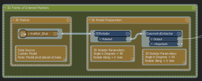
Hi, I'm trying to use point data from a shapefile to accurately place 3D objects (obj) in their correct geographic location, and then outputting the collection to FBX.

I based my approach on the response by @takashi to the following forum question: Adding a 3D model and Geo-referencing it with multiple XY points

It seemed to work really well. However, when comparing the final FBX model to other 3D layers the markers seem to be in the wrong location.

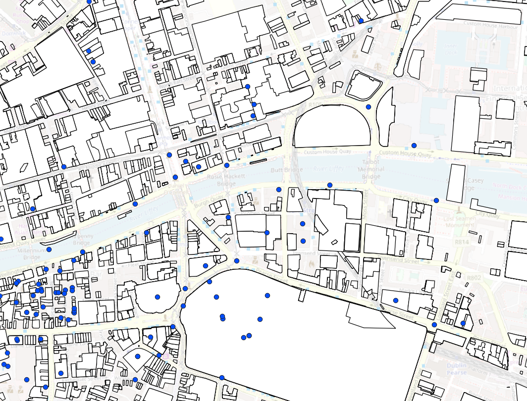
Input from QGIS matches FME 2D Inspector output pictured below.

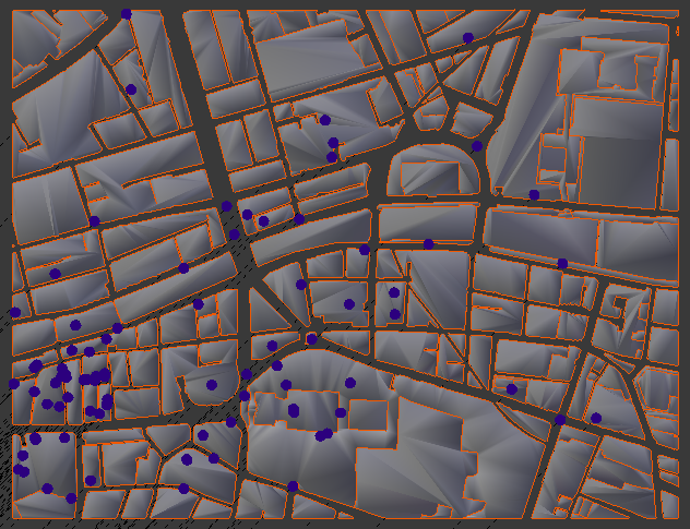
FBX Output in Unity (visualised below against other map layers exported from FME as 3D objects).

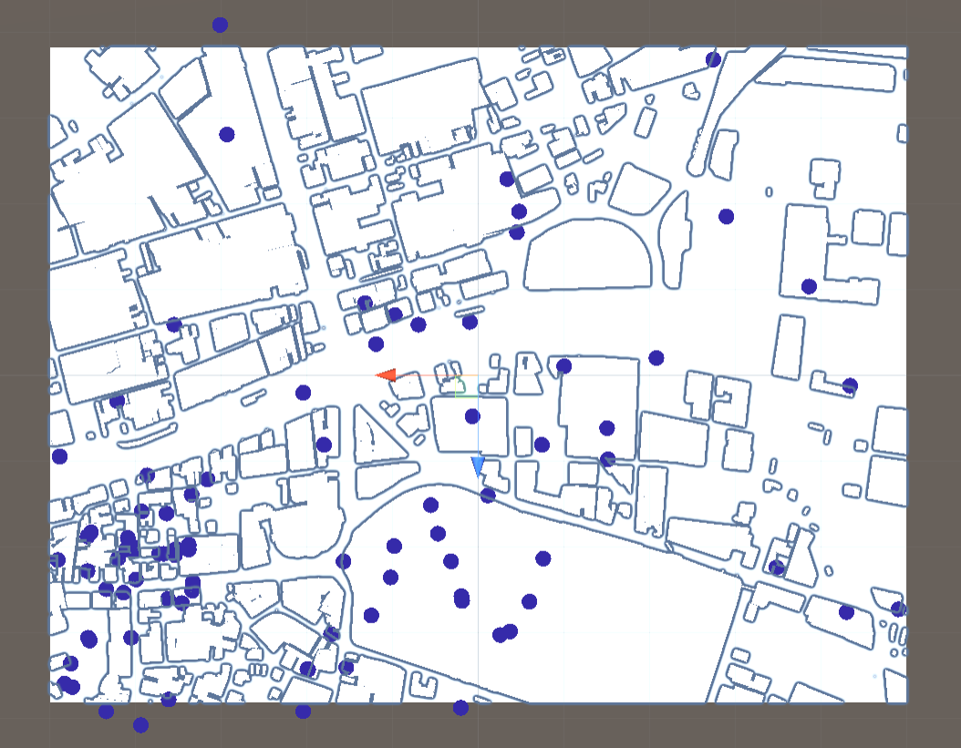
The 3D objects in the FBX output appear to be spread to the north and the south and stretched to the east. This looks like a projection issue but the 2D output is fine so its unclear why the 3D output wouldn't be. Alternatively the problem may be the offsetter, but if that's the case I'm not sure exactly what the problem is.

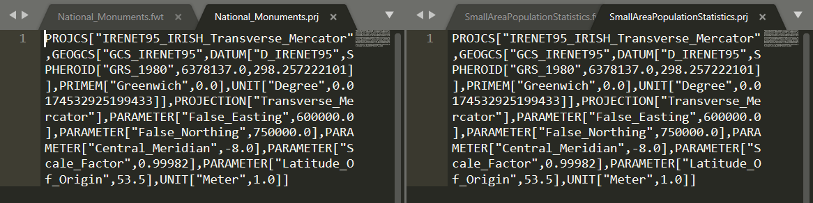
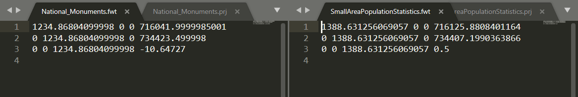
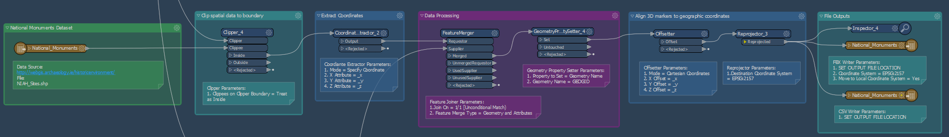
The input shapefile coordinates (clipper boundary and monuments dataset) and the FBX output coordinates are set to EPSG:2157. I also have a reprojector in the flow as that enabled viewing the locations against a basemap in the inspector.

If you have any suggestions that would be much appreciated. If necessary I can arrange to share the FME flow if you are able to assist.

icon

Best answer by virtualcitymatt 5 July 2019, 14:35

View original

3 replies

Userlevel 4
Badge +26

Hmm sounds annoying!

It could be related to the "move to local coordinate" system in the writer. Check the output FBX that the measurements between points are the same in FME (Inspector_4). If the measurements are the same then its the buildings in Unity which are off and if they are different then the points are wrong.

There should also be an additional file output which contains information about restoring the data to the correct location (fme uses file this when reading the FBX back into FME). If you look in this file (it's just a text file) check to see if there has been any scaling applied. This could be where the problem is coming.


It's worth checking out


Hi, thanks for the suggestion @virtualcitymatt This actually helped a lot. I realised that my assumptions about what the 'move to local coordinate' were incorrect. Both the extruded footprints and the markers are processed and exported from the same workspace so I'd expect them to be collocated after export. I did an initial check of exporting the files without selecting 'move to local coordinate' and imported into Blender.

Although far from origin (as expected) the relative positions of the objects were correct. I checked the proj files and the fwt files for both FME outputs:

While the proj files match the fwt files don't. The issue is that the 'move to local coordinate' option maps any input to a 3D coordinate space between [-0.5, -0.5, -0.5] and [0.5, 0.5, 0.5] (see GeoNerds, Breadcrumbs, and 3D Georeferencing). The problem for me is that the implied bounding boxes of my two inputs shapefiles are different so they'll naturally map differently to that local coordinate space.

Ultimately I'm trying to establish a solution that allows me to have control over the translation of outputs. I'd looked at several strategies previously but hadn't yet found a satisfactory solution. Unless are any better suggestion I'll have another look at the Offsetter node.

Userlevel 4
Badge +26

Hi, thanks for the suggestion @virtualcitymatt This actually helped a lot. I realised that my assumptions about what the 'move to local coordinate' were incorrect. Both the extruded footprints and the markers are processed and exported from the same workspace so I'd expect them to be collocated after export. I did an initial check of exporting the files without selecting 'move to local coordinate' and imported into Blender.

Although far from origin (as expected) the relative positions of the objects were correct. I checked the proj files and the fwt files for both FME outputs:

While the proj files match the fwt files don't. The issue is that the 'move to local coordinate' option maps any input to a 3D coordinate space between [-0.5, -0.5, -0.5] and [0.5, 0.5, 0.5] (see GeoNerds, Breadcrumbs, and 3D Georeferencing). The problem for me is that the implied bounding boxes of my two inputs shapefiles are different so they'll naturally map differently to that local coordinate space.

Ultimately I'm trying to establish a solution that allows me to have control over the translation of outputs. I'd looked at several strategies previously but hadn't yet found a satisfactory solution. Unless are any better suggestion I'll have another look at the Offsetter node.

Hi @virtualarchitec,


Glad to hear that it helped, interesting findings. It looks like this guy has had a similar issue, however, there is a tidbit from @daveatsafe where he mentions the 'CommonLocalReprojector' perhaps you could simply fun everything through this and then split it at the end before output (without moving to local coordinate system). I think this is simply offset and no scaling is applied. Warning, everything must have a projection for it to work


Give it a try

Reply