Hi!
I'm looking to create some 3d parallel offsets of existing 3D polylines. My end goal is to actually create a polygon a certain width around a polyline but it must retain the 3d elevations. I've looked into the following tools: Offsetter, OffsetCurveGenerator, Buffer and 3DBufferer. All of these are close however don't quite get me there. The buffer is perfect however is only 2D. I do not know how to then restore the elevations so that it retains its 'parallel figure'. Note that the vertices of the 3D polys have different values, they are not all the same value, ie goes up and down.
Any suggestions?
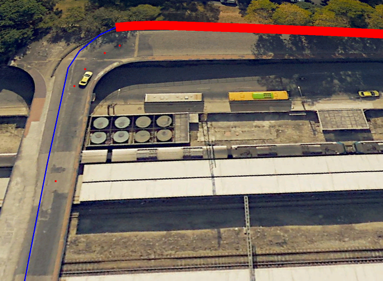
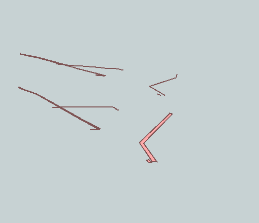
Buffer result: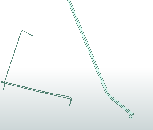
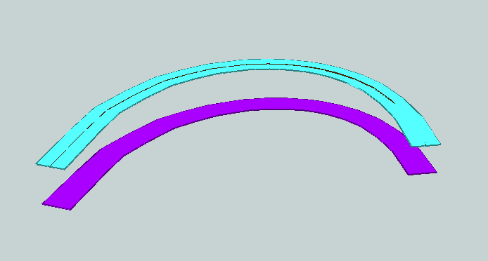
Buffer result 3D view:
Best answer by jdh
View original