Solved

Adding Arrowhead to PDF Output

  • 25 February 2020
  • 5 replies
  • 7 views

Badge +9

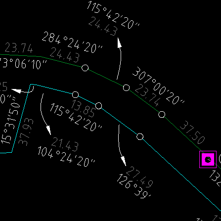
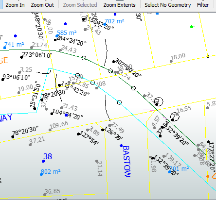
We have a DWG drawing where the arrow heads have been created as a block but the arrow heads are not coming into FME and hence I am not able to output the arrow heads to a PDF.


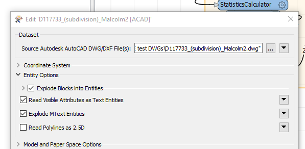
I have exploded the blocks into entities but still no luck.


Is there a way to recreate the arrow heads when outputting to PDF or bringing the data in from the DWG.

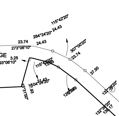
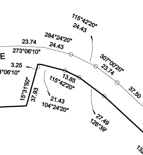
Attached is a sample drawing to help understand what I am trying to achieve.

Any assistance would be appreciated.

icon

Best answer by debbiatsafe 25 February 2020, 23:19

View original

5 replies

Userlevel 3
Badge +17

Hi @deanhowell

The arrowheads in your sample file are polylines with a variable width at the start and end vertices. FME does read and store line width information on features but does not display these in Data Inspector. This information is more used for round-tripping from DWG to DWG.

2019.0 also added the ability to read and store width information on the start and end vertex of a polyline. For more information, please see the documentation on the format attributes autocad_start_width and autocad_end_width: at https://docs.safe.com/fme/html/FME_Desktop_Documentation/FME_ReadersWriters/acad/Lines.htm

You can try to recreate the arrowheads using the information stored in the format attributes mentioned above. Attached is one method that attempts to create arrowhead polygons from polylines with variable line width. ArrowheadFromVariablePolylineWidth.fmw

Badge +9

Hi @deanhowell

The arrowheads in your sample file are polylines with a variable width at the start and end vertices. FME does read and store line width information on features but does not display these in Data Inspector. This information is more used for round-tripping from DWG to DWG.

2019.0 also added the ability to read and store width information on the start and end vertex of a polyline. For more information, please see the documentation on the format attributes autocad_start_width and autocad_end_width: at https://docs.safe.com/fme/html/FME_Desktop_Documentation/FME_ReadersWriters/acad/Lines.htm

You can try to recreate the arrowheads using the information stored in the format attributes mentioned above. Attached is one method that attempts to create arrowhead polygons from polylines with variable line width. ArrowheadFromVariablePolylineWidth.fmw

Thanks @debbiatsafe you are a champion :)

Badge +9

Hi @deanhowell

The arrowheads in your sample file are polylines with a variable width at the start and end vertices. FME does read and store line width information on features but does not display these in Data Inspector. This information is more used for round-tripping from DWG to DWG.

2019.0 also added the ability to read and store width information on the start and end vertex of a polyline. For more information, please see the documentation on the format attributes autocad_start_width and autocad_end_width: at https://docs.safe.com/fme/html/FME_Desktop_Documentation/FME_ReadersWriters/acad/Lines.htm

You can try to recreate the arrowheads using the information stored in the format attributes mentioned above. Attached is one method that attempts to create arrowhead polygons from polylines with variable line width. ArrowheadFromVariablePolylineWidth.fmw

Hello again @debbiatsafe, FYI I ran your workbench in both 2019.2 and 2020.0 and got two very different results where the arrow heads are reversed. 2020 fixes the textStroker rotation issue but has introduced a different issue :)


Userlevel 3
Badge +17

Hello again @debbiatsafe, FYI I ran your workbench in both 2019.2 and 2020.0 and got two very different results where the arrow heads are reversed. 2020 fixes the textStroker rotation issue but has introduced a different issue :)


It looks like the order in which vertices are created was changed in 2020.0 for features coming out of the Bufferer, which caused changes in the output.

What the VertexCreator and VertexRemover transformers does in the workspace is manipulate the shape of the buffer (a rectangle) by replacing the coordinates at one of the vertices and removing another vertex to create the desired shape (triangle).

Unfortunately, this method depends on the order of vertices being in a specific order. You will have to modify the VertexCreator and the VertexRemover insert and remove the correct vertices. I believe you can also delete the second VertexRemover. Once these have been changed, the output should appear correctly.

Badge +9

It looks like the order in which vertices are created was changed in 2020.0 for features coming out of the Bufferer, which caused changes in the output.

What the VertexCreator and VertexRemover transformers does in the workspace is manipulate the shape of the buffer (a rectangle) by replacing the coordinates at one of the vertices and removing another vertex to create the desired shape (triangle).

Unfortunately, this method depends on the order of vertices being in a specific order. You will have to modify the VertexCreator and the VertexRemover insert and remove the correct vertices. I believe you can also delete the second VertexRemover. Once these have been changed, the output should appear correctly.

Thanks again @debbiatsafe, I will stand by my first comment - you are a champion :)

Reply