Question

Set identifier to vertice

  • 5 December 2019
  • 3 replies
  • 0 views

Badge +14
  • Contributor
  • 120 replies

I would like to try the following:

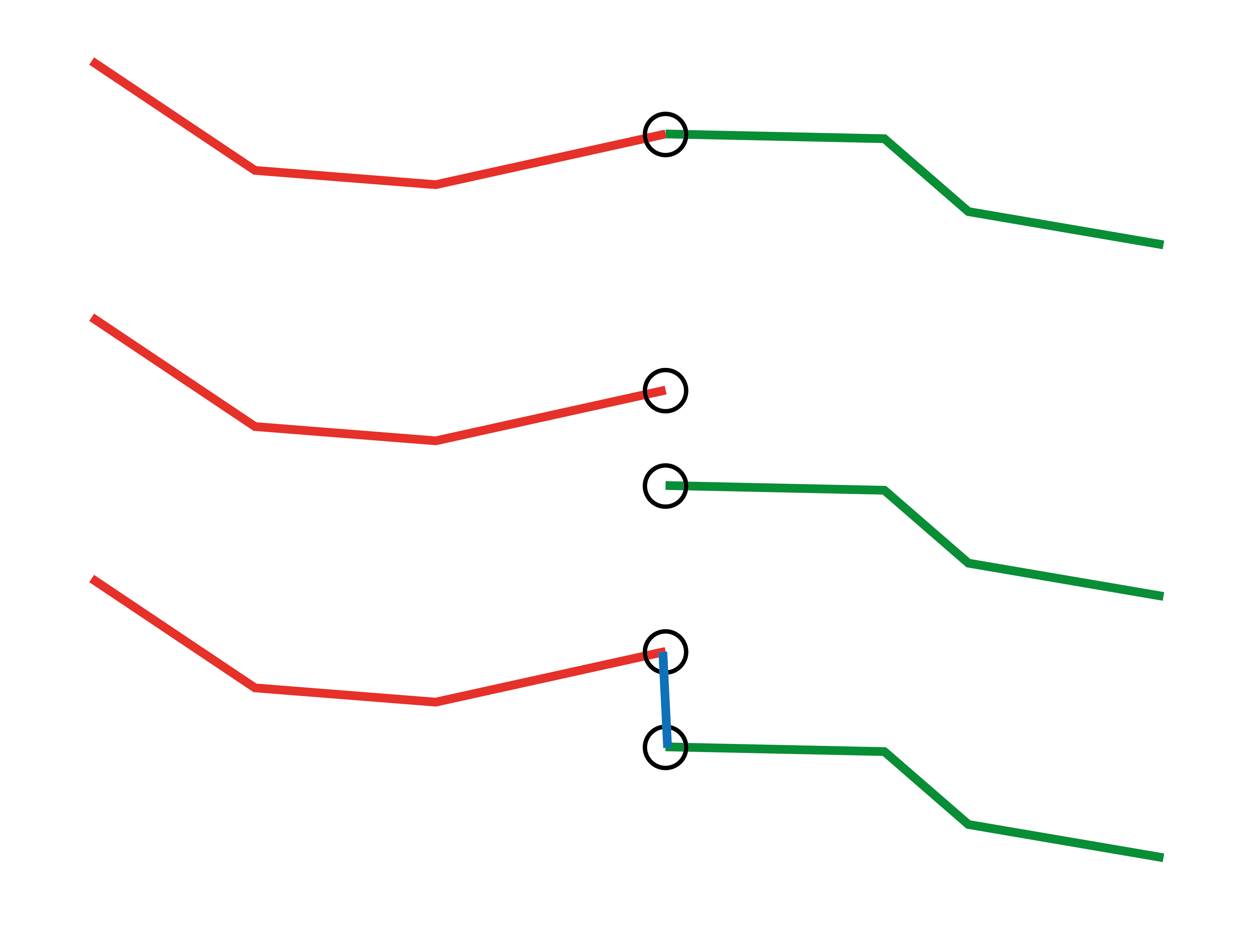
Identify where lines touch and set an unique id to these overlapping/touching vertice (as in points, I hope I get the lingo right here).

I will then move one of the lines with an OffsetCurveGenerator. Which means that the two lines wont be touching any more.

Finally I would like to use the identifiers at the end of both lines as pairs and create a new line between the two.

Q: How can I set a unique identifier to a vertice, similar to using a counter to set a id to the whole feature?

Or is there a much simpler way to get the result I want?


3 replies

Userlevel 4

You can use the TopologyBuilder to create nodes with a unique _node_number at each line intersection. Each output line segment will get an additional two attributes _from_node and _to_node to indicate the relationship.

You can use the VertexCreator to build the line after the Offsetter.

Badge +3

There are a few methods. Variations of TopologyBuilder, Intersector and LineOnLineOverLayer will output common Nodes/Points, although I hate dealing with some of the artefacts that come out of these such as when lines cross or happen to have a coincidental mid-vertices where Points/Nodes also get generated on these (FME Version dependent for TopologyBuilder)

An alternative method is 2 x Snippers(Vertex Mode) that transforms each line into their respective Start and End Points. Using Matcher on the output of the 2 Snippers will assign a "Match ID" where 2 different end points touch. The advantage with these is it keeps 2 separate end points (Output on the Matched Port) rather than dissolving it to a single Node feature, but you can draw a Line using LineBuilder by Sorting on the Match ID. It also will at the same time output a Single Dissolved Node on the SingleMatched Port. Using Snipper and Matcher guarantees that the End Points, and the End Points only, are what get spatially related to each other.

There is more Transformers involved in getting the End Points/Nodes out than just running a single TopologyBuilder transfomer, but at least in FME2018 it is what I've found out of all the above methods gets the most generalised and accurate form of End to End Topology and outputs somewhat easier to use feature sets.


Badge +14

There are a few methods. Variations of TopologyBuilder, Intersector and LineOnLineOverLayer will output common Nodes/Points, although I hate dealing with some of the artefacts that come out of these such as when lines cross or happen to have a coincidental mid-vertices where Points/Nodes also get generated on these (FME Version dependent for TopologyBuilder)

An alternative method is 2 x Snippers(Vertex Mode) that transforms each line into their respective Start and End Points. Using Matcher on the output of the 2 Snippers will assign a "Match ID" where 2 different end points touch. The advantage with these is it keeps 2 separate end points (Output on the Matched Port) rather than dissolving it to a single Node feature, but you can draw a Line using LineBuilder by Sorting on the Match ID. It also will at the same time output a Single Dissolved Node on the SingleMatched Port. Using Snipper and Matcher guarantees that the End Points, and the End Points only, are what get spatially related to each other.

There is more Transformers involved in getting the End Points/Nodes out than just running a single TopologyBuilder transfomer, but at least in FME2018 it is what I've found out of all the above methods gets the most generalised and accurate form of End to End Topology and outputs somewhat easier to use feature sets.


Thats a clever solution! As you say clean from all other artefacts. Will try this.

Reply