
I am able to create 3d room by using floor elevation. And for stairs i also 2d shapefile polygon with from 2 to floor munber and junctions with level info, but how to elevate it diagonally in FME for KML output??

Is it possible to create 3d stairs using single square polygon in 2d shapefile with elevation of each floor.
 +8
+8
Hi @shweta , are your stairs (each step) individual polygons or a single polygon for the entire structure.
Hi @shweta , are your stairs (each step) individual polygons or a single polygon for the entire structure.
Hello @gisinnovationsb, i have single polygon for stair area on each floor.. No stepwise polygon available.
+8
Hello @gisinnovationsb, i have single polygon for stair area on each floor.. No stepwise polygon available.
Can I assume that they are perfect rectangles?
Can I assume that they are perfect rectangles?
Yes they are rectangles

Userlevel 4
 +25
+25
- Safer
- 2399 replies
-
22 April 2016

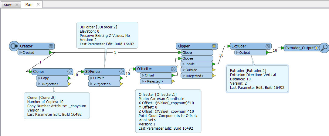
My first thought is this:
- Assume you want N stair steps...
- Use a Cloner to clone the original feature N times
- Add a 3DForcer to set an original z value (even if it is zero the features need it)
- Offset each feature in the direction of alignment
- Offset in the direction of alignment by X * _copynum (where X is width of stair)
- Offset in the Z direction by Y * _copynum (where Y is the height of each step)
- Clip all the features using the original area as the clip boundary
- Extrude all the features by Y
The tricky part is the direction of alignment. I managed to create a workspace fairly easily, but assumed an East-West orientation. If it's not you would need to calculate different X/Y offsets.
You can download my workspace here: stairbuilder.fmw
@Mark2AtSafe Thanks for WB.
Yes it worked but only for single orientation.
Is there a way to put that a condition that all stairs are in rectangle like shape (few are curved) which means each polygon length is always greater than width. So we can define that above WB flow should work from width (which is always small) of each polygon.
OR
We can define few steps in above WB so that it should work from width of polygon with country driving direction.
Because in my data stairs are in all direction combinations E-W, N-S, W-E, S-N, NE- SW etc..

Userlevel 2
 +17
+17
- Contributor
- 7539 replies
-
2 May 2016

@Mark2AtSafe Thanks for WB.
Yes it worked but only for single orientation.
Is there a way to put that a condition that all stairs are in rectangle like shape (few are curved) which means each polygon length is always greater than width. So we can define that above WB flow should work from width (which is always small) of each polygon.
OR
We can define few steps in above WB so that it should work from width of polygon with country driving direction.
Because in my data stairs are in all direction combinations E-W, N-S, W-E, S-N, NE- SW etc..
Hi @shweta, I think probably there is a way to determine the longer side and shorter side of a rectangular polygon, but I'm afraid that it's difficult to find out a way to determine the up/down direction. Do the source polygon features have attributes which can be used to determine the direction?
 +3
+3
if stair area is width of a single step then that gives us the direction, yes?
Hi @shweta, I think probably there is a way to determine the longer side and shorter side of a rectangular polygon, but I'm afraid that it's difficult to find out a way to determine the up/down direction. Do the source polygon features have attributes which can be used to determine the direction?
@takashi We do have network (line feature) crossing this stairs polygon. But then i need to make these Network also slanting like stair network at start junction on one level and end junction on another level.
Then query need to make like if Network start junction is present at one of the width of stair polygon then stair should start from there and stair should end either down or up depend on Network junction on below level or above level.
i have the idea but not able to figure out how it will be done in FME.
+8
Perhaps you could add an attribute to your table (I am speaking in shapefile language) with a value Up or Down (?)
Userlevel 2
+17
- Contributor
- 7539 replies
-
4 May 2016
Hi @shweta, I think probably there is a way to determine the longer side and shorter side of a rectangular polygon, but I'm afraid that it's difficult to find out a way to determine the up/down direction. Do the source polygon features have attributes which can be used to determine the direction?
like this image? green: stair polygon, red: network line, blue: junction points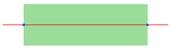
Userlevel 2
+17
- Contributor
- 7539 replies
-
4 May 2016
Hi @shweta, I think probably there is a way to determine the longer side and shorter side of a rectangular polygon, but I'm afraid that it's difficult to find out a way to determine the up/down direction. Do the source polygon features have attributes which can be used to determine the direction?
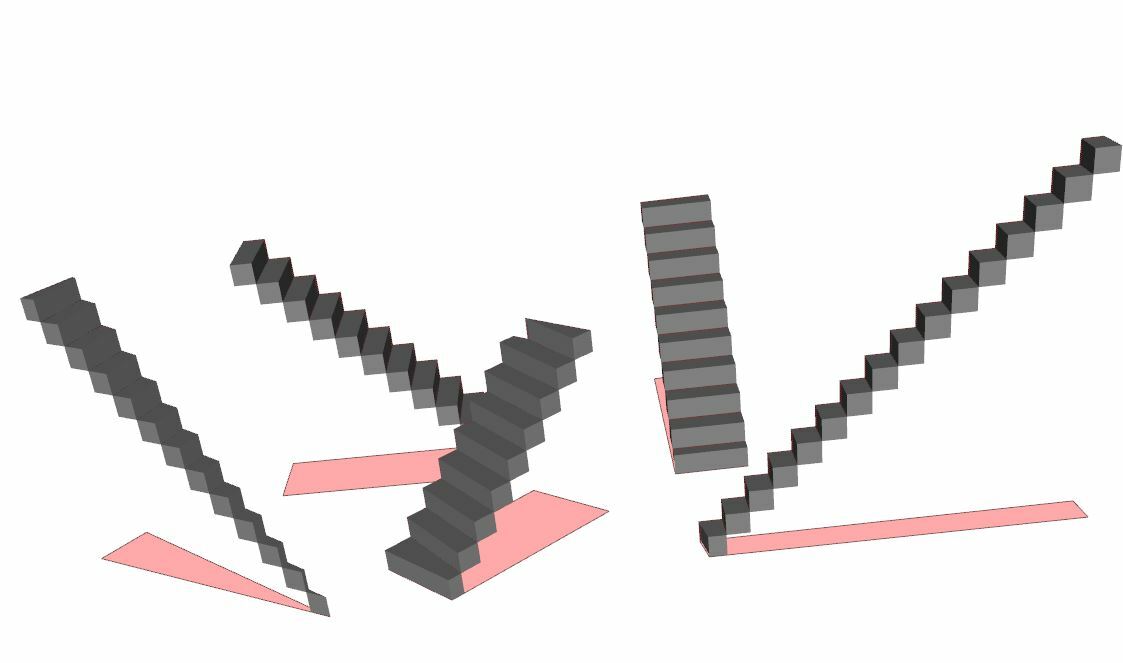
Just an idea. If the line segment between the two junctions represents the up/down direction of the stairs, this may be a possible way.
- Create a line segment connecting the two junctions, directed from the below level to the above level.
- Calculate the angle of the line segment with the AzimuthCalculator from FME Hub.
- Merge the angle to the stair polygon.
- Create 3D stairs with @Mark2AtSafe's method, using the Offsetter with "Polar Coordinate" mode. This mode has been introduced in FME 2016.
+8
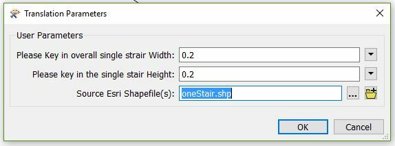
Hi @shweta , could you please try the attached workspace, you need to insert the length and height of the steps. Also please change the reader to yours and add the writer of your choice.
strairs3.zip
@gisinnovationsb, @takashi i will try both of your methods and will check which one will suitable for my source type.. Thanks a lot to both of you.
Hi @shweta , could you please try the attached workspace, you need to insert the length and height of the steps. Also please change the reader to yours and add the writer of your choice.
strairs3.zip
@gisinnovationsb can you please convert this workbench in FME 2015.1 version. As presently i am using this version..
Thanks.
+8
@gisinnovationsb can you please convert this workbench in FME 2015.1 version. As presently i am using this version..
Thanks.
@shweta , the workspace was generated with 2016.1 , I am not sure if it would work on 2015. Let me see if we have any machines at the office still running 2015.1 which I doubt. Alternatively you could test it out on 2016.1 by using a trial version before upgrading your machines as well.
+8
Hi @shweta , could you please try the attached workspace, you need to insert the length and height of the steps. Also please change the reader to yours and add the writer of your choice.
strairs3.zip
Hi @shweta,
Please try with the newly updated version. I did not compile it properly last time . The missing transformer is from the HUB; the DistanceMarker.
Please try it out, install it and overwrite previous installation. You will have to input the Run and Rise of the steps though because I am not sure on what are your specifications.
I would appreciate your input if you face any problems.
3dstairscreator.zip
Thanks.
Lyes
Reply
Enter your username or e-mail address. We'll send you an e-mail with instructions to reset your password.