Question

Assign value to start- and endpoint

  • 25 September 2013
  • 13 replies
  • 9 views

I have a dataset of polylines from an ArcGIS database with a 2D geometry and the z-values for the startingpoints and endpoints stored in its attributefile as Z-Start and Z-End. I need to assign those values to the z-value of the first and last points in the polyline in order to export the dataset as a 3D dwg-file.


There is nothing in the datasets attributes that indicates wich is the beginning or the end of the polyline but looking at the datasets geometry for each polyline in the Data Inspector shows that the order of the including points follows the drawingorder in ArcGIS


I cannot find a way that could count the number of points in the geometry of the polyline or a way to assign the z-values.


Is this doable?


13 replies

Hello,


in the first step you could use the 3DForcer to assign z-values...


Best regards,


Stefan
True, but thats just the easy part :-)
Userlevel 4
Badge +13
Hi,


Maybe this can help....


https://www.dropbox.com/s/zi74dzzfe510nxk/Assign%20value%20to%20start-%20and%20endpoint.fmw


Userlevel 4
Hi,


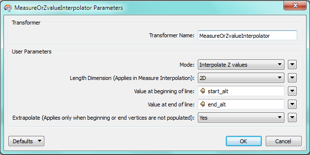
there is a custom transformer called MeasureOrZValueInterpolator on the FME Store that I believe does what you need. It will assign given Z-values for the first and last vertex and interpolate the Z-value for all vertices in between.


David
Itay, when extracting the coordinates of the line, you actually use the index-parameter in the CoordinateExtractor to start from the beginning or from the end?


best regards Henrik
Userlevel 4
Badge +13
Hi Henrik,


when extracting the coordinates of the line, you actually use the index-parameter in the CoordinateExtractor to start from the beginning or from the end?


Correct, index 0 = start and index -1 =end
David, this might be helpful for populating the breakpoints inbetween if there are any, thanx
Thank you all, I think I can solve it now. I actually started doing a GeometryExtraction as WKT and was thinking of assigning z-values using regex and then use GeometryReplacer
Userlevel 4
Badge +13
well I guess that depends on how FME reads the line feature, since you chop it into individual vertices, the vertices order should remain intact.
Userlevel 4
Hi,


just to be clear, I suspect you can replace your whole process with the MeasureOrZValueInterpolator, whether they contain more than 2 vertices or not:


David
Userlevel 4
Badge +13
Well, if you look in the store transformer you will see it uses many more transformers, that can lead to lessened preformance in comparison to the suggested process.


That is, naturally, if you are satisfied with the results of the suggested process.
Userlevel 4
It has not been my experience that the number of transformers necessarily bears any relation to performance. I wouldn't be able to say which solution was more efficient before having tested both with the data in question.


David
Userlevel 2
Badge +17
Hi,


One possible approach. I don't think it needs so many transformers when using FME 2013 SP2+.


  1) Calculate common constants. dz = (Z-End - Z-Start) len1 = Length of the original line   2) Split the line into individual line segments, calculate their lengths. len2[i] = Length of line segment (i) (i = 0, 1, 2, 3...)   3) Calculate z-value of the first node of every segment. z[0] = Z-Start z[i] = z[i - 1] + dz * (len2[i - 1] / len1)   (0 < i) * linear interpolation   4) Transform every segment to each first node, append the end node (z = Z-End), change them to 3D points, and connect them into a line.   If you are using FME 2013 SP2 or later, "Mutliple Feature Attribute Support" option of the AttributeCreator can be used effectively in 3). FME Evangelist > FME 2013-SP2: Excelsior! > 4) AttributeCreator Updates http://evangelism.safe.com/fmeevangelist115/


Takashi

Reply