Question

Shifting utilities point & line objects based on cadastral boundaries


Hi All

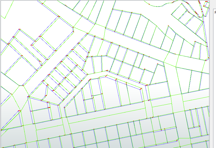
I have numerous map layers containing point & line objects that were created using cadastral boundaries as a reference. I'd like to move to a more accurate version of the cadastre and need to shift the utilities point and line objects into the same relative location. Any advice appreciated.

Regards

Craig Townsend


23 replies

Badge +2

Hi,

Do you know how much distance you have to move? or is it some kind of vector georeferencing?

Can you add some screenshot for better understanding

Badge +8

Hi @craig ,

Please try the AnchoredSnapper;


http://docs.safe.com/fme/2016.1/html/FME_Desktop_D...

Hope this helps.

Hi,

Do you know how much distance you have to move? or is it some kind of vector georeferencing?

Can you add some screenshot for better understanding

Hi Pratap

It's not a consistent shift across the cadastre so the distance will be quite variable. In some places a shift won't be required, in others it may range up to 15mts.

I've attached a screenshot. Red is the old cadastre, blue is the new cadastre and the pink lines & points represent pipes & manholes.capture.jpg

Regards

Craig

Hi @craig ,

Please try the AnchoredSnapper;


http://docs.safe.com/fme/2016.1/html/FME_Desktop_D...

Hope this helps.

Thank you gisinnovationsb, I'll look into this one.

Regards

Craig

Badge +2

Hi,

Use Offsetter initially and move entire data to the nearest point (seems to be same at all locations) and then use AnchoredSnapper for accurate movement of features

Hi,

Use Offsetter initially and move entire data to the nearest point (seems to be same at all locations) and then use AnchoredSnapper for accurate movement of features

Hi Pratap

I'll look into the offsetter, the screenshot may not have been clear enough but there are subtle variances in the 2 cadastre layers.

Badge +2

Hi Pratap

I'll look into the offsetter, the screenshot may not have been clear enough but there are subtle variances in the 2 cadastre layers.

My intention of using offsetter is to bring the features within small radius such that spatial query by anchorsnapper will be effective

Userlevel 1
Badge +12

Hi Craig,

That's some pretty ugly cadastral offset for what looks like residential. So you want to rubber sheet the utilities based on the cadastral move?

If so, you probably need the distance between the marks between the two cadastral dataset. You could try the anchorsnapper and there a few different ways there. If that is not going to cut it, I would turn each boundary into a single line and then do a spatial comparison and compare length and angle with some allowance between the two datasets.

I do have a process that does that, and increases reliability by checking network relationships. It designed for three waters, so the cadastre should be a breeze because the interrelationship between features is pretty much guaranteed. I can't give the script out, but if you can provide sample data, I certainly can test it out and if it works out, I would run the whole lot.

Cheers,

Todd

Badge +8

Thank you gisinnovationsb, I'll look into this one.

Regards

Craig

@craig, if you could share some data as @todd_davis mentioned that would be great,

Badge +3

LIke you said it is not a consistent transformation.

That will make it pretty hard to find a single general formula to shift the points and lines.

I wuold try shifting the node as many times as the network it is connected to crosses a boundary. Shift by the distance the boundary moved in the direction of the connected network.

You would need to have a nested iterative process to shift each point as many times as it has connections.Top the number of points, child nest number of connections.

Calculating ditance and moving along a vector is prrty easy.

Badge +16

This is one case where FME on its own might not be the best solution - full disclosure, I work for Esri, but I know Safe will appreciate the candor. If you have ArcGIS Desktop Advanced then take a look at Generate Rubbersheet Links and Rubbersheet Features. Just the links from the first tool can be used to warp non-linear features with the RubberSheeter transformer. That would be the easy-button approach anyway. If you are a perfectionist you would go the route of using the survey observations of your cadastre to correct your parcel boundaries then borrow those shifts to adjust the dependent features. ArcGIS has that workflow too with a parcel fabric.

Badge +3

We also use ArcGis.

And am known with the spatialadjustment toolbar: ruubbersheeting, affines, projective etc. etc. (mostly used on creatively dispalced autocad drawings or drawings ripped from pdf's etc..)

I don't think that actually answers the posed question though. The relative part mostly..

Badge +5

If you want to do this in FME, I think it comes down to whether the features on the cadastral layers have ID numbers where you can identify each feature in both versions.

If you can then what you need to do is create a line feature between the original and new points on each feature, to create control features. Then you can rubbersheet the pipeline data.

I've attached a workspace - cadastraloffset.fmw that does that. It only has 1 cadastral feature, and it assumes there are the same number of features on each cadastre layer in the same order. If not, you should remove features that don't appear in the other layer (Matcher transformer?) and sort the data into order (Sorter).

I'm about 80% certain this would work. My example has a fixed offset, whereas yours is variable, but that's just because it was easier to create an example like that. It will still work.

Otherwise I would - reluctantly - agree with Bruce. Others have suggested the AnchoredSnapper, but I don't think this is a viable solution for your problem. You don't want to snap the pipeline and you don't really want to snap the second cadastral dataset. You just need to know what the offsets are between the two, and use that to rubbersheet the pipeline.

Badge +22

Assuming a pure FME approach (I have some workspaces where I create the links in arcmap georeference toolbar, but then read the link file in fme and do the manipulation there).


Assuming the cadastral layer doesn't have common IDs between versions (if they do, go with Mark's approach).


I would get the nodes for the cadastral layers (TopologyBuilder) and use the NeighbourFinder to identify the closest new node to each old node and then build control features (VeretxCreator) for use in the RubberSheeter.


If you have more complicated intersections then in the snapshot (where the new node might be closest to a non-corresponding old node), then things like the number of segments on the node, or the angle of the segments could be used to correctly correspond new nodes to old nodes.


Thank you all for your ongoing responses, much appreciated.

The following gives a little more background into the issue I'm facing.

Prior to my time, the organisation decided to maintain its own cadastral/parcel fabric. This was done using less than ideal bearing and distance tools, digitizing, and some 'hand drawing' thrown in for good measure.

Polygons were created in the land parcel layer to represent 'artificial' boundaries around infrastructure items. Road corridors were also 'combined' into the layer. Many consequent map layers (several hundred or more) were developed using the 'in-house' parcel fabric as a reference.

To reduce the ongoing overhead of having to maintain this cadastre, it is our intention to adopt government maintained/supplied cadastre which is far superior in its spatial accuracy than our own.

We're also encountering issues as we attempt to consume spatial data from other government departments or external sources due to the significant difference in spatial accuracy.

Any spatial analysis is problematic to say the least.

I use MapInfo, QGIS and FME and also have access to ArcGIS.

I've attached clipped datasets of an example area.

Regards

Craig

datasets.zip

Badge +8

@craig, if you could share some data as @todd_davis mentioned that would be great,

Hi @craig,


I took a look at the data, if we compare the old and new cadatral data, we can see that the shifts are not heterogeneous. The lines need to have a high degree of accuracy when it comes to finding them back on the ground.


To play safe, I would try to look for the surveyed points for the lines and re-generate the lines using FME. That would be more accurate than using any other methods in my point of view.


Do you have the actual coordinates of each point?


Cheers.

Lyes


Hi Lyes

I've used FME's coordinate extractor to create points from vertices and attributed them with x & y coords.

Regards

Craig

Hi Lyes

I've used FME's coordinate extractor to create points from vertices and attributed them with x & y coords.

Regards

Craig

But I've just noticed that I don't get a point for every vertice.

Badge +8

Hi @craig,


I took a look at the data, if we compare the old and new cadatral data, we can see that the shifts are not heterogeneous. The lines need to have a high degree of accuracy when it comes to finding them back on the ground.


To play safe, I would try to look for the surveyed points for the lines and re-generate the lines using FME. That would be more accurate than using any other methods in my point of view.


Do you have the actual coordinates of each point?


Cheers.

Lyes


I meant coordinates from a surveyor or accurate GPS (sorry for the misundertanding)

Badge +2

Hi,

I have prepared workbench based on the data you have provided and attached. I have made only to New and Old Cadastre . I have reprojected the data and checked in viewer as I don't have mapinfo. Have a look and let me know your views such that geo-referencing for other features can look after

vector-georef.fmw

Userlevel 1
Badge +12

Had a look at this and fired a couple of scripts over it. I would suggest that if you do plan to go down this path that you spend a significant time with planning it and testing. I did what I mentioned above but there are several things I would add if I was doing this for an official outcome. As I was checking line against lines, rather than parcel against parcel, I said that the boundaries couldn't exceed 20% difference in length but I think a maximum angle difference is also very important. You actually don't want to take into account some of the real erroneous data, as it provides a skew. I also found that the natural boundaries (in my approach) caused a bit of difficulty and would need to be taken into account.

The data is vastly different with significant vertex difference and that caused some trouble for me.There are a few error in here as well and I will admit I deleted quite a few around curve/natural boundaries due to the large difference between the datasets

Attached are the movements between the layers and the what the pipes manholes look like after going through rubbersheeter set to distance 30output.zip

Hi,

I have prepared workbench based on the data you have provided and attached. I have made only to New and Old Cadastre . I have reprojected the data and checked in viewer as I don't have mapinfo. Have a look and let me know your views such that geo-referencing for other features can look after

vector-georef.fmw

Hi Pratap

Your workbench results look quite good. Some sub-centimetre differences but this is not critical with regards to moving the pipes or manholes.

Had a look at this and fired a couple of scripts over it. I would suggest that if you do plan to go down this path that you spend a significant time with planning it and testing. I did what I mentioned above but there are several things I would add if I was doing this for an official outcome. As I was checking line against lines, rather than parcel against parcel, I said that the boundaries couldn't exceed 20% difference in length but I think a maximum angle difference is also very important. You actually don't want to take into account some of the real erroneous data, as it provides a skew. I also found that the natural boundaries (in my approach) caused a bit of difficulty and would need to be taken into account.

The data is vastly different with significant vertex difference and that caused some trouble for me.There are a few error in here as well and I will admit I deleted quite a few around curve/natural boundaries due to the large difference between the datasets

Attached are the movements between the layers and the what the pipes manholes look like after going through rubbersheeter set to distance 30output.zip

Hi Todd

Thank you for looking into this, I appreciate your time. What's becoming apparent is that it's going to be a hard nut to crack due to the reasons you've highlighted. I'm thinking I may need to process much smaller geographic areas.

Regards

Craig

Reply