Question

autocad fill color


Badge +6

Hi Guys,


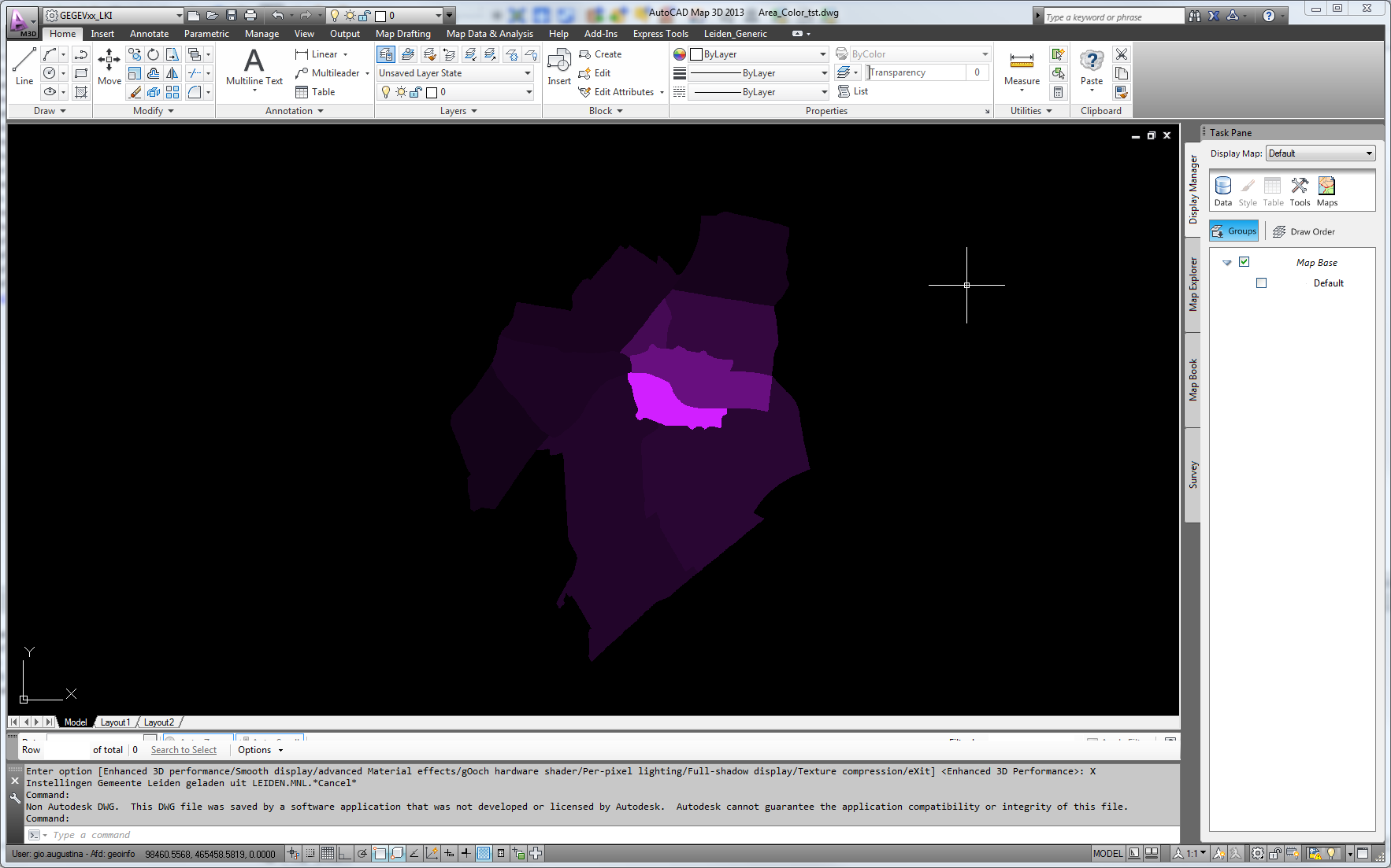
I convert a shape file in an autocad file and want to build areas which have different colors...

i give the autocad_color the index of the different colors depending on an other unique attribute and the border lines of the areas has exactly this right color...

but i have problems with the fill....the fill always (either i give an color in the dwgstyler or use these gradient_color format attributes) comes with the fill color red (which is the default color index 10 which is set in the destination format attribute)

So how i can I do this that the fill of the area has the same color as the border line (autocad_color) has now?


Thank you and Greetz


Franco

11 replies

Badge +3
Hi,


If you use dwg Styler and select a fill patern, these will be hatches. Solid colour you would select solid hatch.


You must then select Area Entitiy Type = Hatch With Fill Pattern.


Then it will show the colours you chose. It will automaticaly override the default color.


This


@Evaluate(1/(@Value(WIJKCODE)*1.0+1)*0.823529),@Evaluate(1/(@Value(WIJKCODE)*1.0+1)*0.12549),@Evaluate(1/(@Value(WIJKCODE)*1.0+1)*1)


yields this dwg


Badge +3
btw the fme transformers accept color  in  r,b,g as 0-1. As  in the expression above.
Badge +6

Hmmm....

i don't understand completely.....now i have set an index for the color and write it in the attribute autocad_color......so i can get the borderline......and the fill?...is there any format attribute i have to place the index for the color or it is enough to set the right Area Entity type?


Greetz


Franco
Userlevel 2
Badge +17
Hi Franco,


You can set an attribute which stores color value to the "Color" parameter of the DWGStyler. But, note that the color value should be comma-separated normalized RGB component values.


For example, the color value of Autocad Color Index "30" (R=255, G=127, B=0) will be "1,0.498039,0" (i.e. 255/255, 127/255, 0/255).


So, if you need to set a color equivalent to an Autocad Color Index, you may have to convert the index to a color value.


I found a web page containing a table of Autocad Color Index and RGB values.


AutoCAD Color Index (ACI) RGB equivalents (http://www.isctex.com/acadcolors.php)


Takashi
Badge +3
yes, format of color is like fme writes them.


If u use a colorsetter and clikc a color you see the format.


 i.e.  r,g,b=0.2,0.3,0.45 etc.


You can use a creator to calculate and format the string (as in my example).


You don't need to set any format attribute after the styler to get the dwg writer to create it.


Badge +3
my example create a color graduation (based on r= 0.823529, g= 0.12549, b=1) A purple gradient... ;)
Badge +6

I managed to add SummaryInfo Comments (also known as DWG properties) to DWG files (created by FME Desktop) using ObjectDBX in a Windows Powershell  post process and wonder if it is possible to do it directly in FME Desktop:

$srcDir = "C:\DWG\infiles\"
$tgtDir = "C:\DWG\outfiles\"
$errorFile = 'C:\DWG\error.log'
$comments = 'C:\DWG\comments.csv'
 
$AutoCad = New-Object -ComObject Autocad.Application
$AcadVer = $AutoCad.ActiveDocument.GetVariable("ACADVER")
$AcadVer = $AcadVer.Split(".")[0]
$DbxId = "ObjectDBX.AXDbDocument."+$AcadVer
$Dbx = $AutoCAD.GetInterfaceObject($DbxId)
 
foreach($line in Get-Content $comments -Encoding UTF8)
{
  $data = $line.Split(";")
  Write-Host $data[0]
  try{
    $Dbx.Open($srcDir+$data[0]+".dwg")
    $Dbx.SummaryInfo.Comments = $data[1]
    $Dbx.SaveAs($tgtDir+$data[0]+".dwg")
  }
  catch{
    $error_msg = $srcDir+$data[0]+".dwg"
    Out-File -FilePath $errorFile -Append -InputObject $error_msg
Write-Host "Error: ",$data[0]
  }
}

comments.csv:

4233-15_1;Last Change - VA40:21.10.2020
4234-31_3;Last Change - VA40:21.10.2020
4234-31_4;Last Change - VA40:21.10.2020
4234-32_1;Last Change - VA40:21.10.2020

As a workaround/hack in FME Workspace, I added a temporary DXF header with the included comments to my DWG Writer , but unfortunately this only works with "AutoCAD DWG Writer" and not with "RealDWG Writer" anymore (FME Desktop 2020.2 Windows 10/64bit).


2 years ago I had no problems adding DXF headers to DWG files using RealDWG, but the current FME version can't add these headers with the REAL driver. I really need the RealDWG Writer to prevent these annoying TrustedDWG messages 😉 


Badge +6
and for completeness...here is a link where an excel file with autocad color index and RGB numbers is downloadable!


https://onedrive.live.com/view.aspx?resid=CB948AEB4728C76D!1356&app=Excel&authkey=!AGqmRz6KTXsCdWg


Greetz


Franco
Badge +6

Additional Question......now i have all areas in right color....but when all areas should have a black borderline...can i only solve this when i write the borderline as lines also?...but then i have double data....another solution?

Thx

Franco

Userlevel 2
Badge +17
As far as I know, there is no way to set border color of hatch entity independently from setting fill color. I think you will have to create another set of polygon or line features to draw borders.


Thanks for sharing the Excel table. As an example for calculating color values, I created a workspace which reads your table. (https://drive.google.com/file/d/0B0ufVP2t0eApZ0ttVzZ4d194dzA/view?usp=sharing)


Badge +6

Perfect!!!

Thank you very much!!!

Reply